
Summary of Contents for clicMONITOR CcM1-DC
- Page 1 MORE THAN METERING USER MANUAL Take care of your planet... clicmonitor.com take care of you...
-
Page 2: Table Of Contents
4.1 Identification 5 Installation 5.1 Step 1: Safety 5.2 Step 2: Disconnection of the current line 5.3 Step 3: Connection of the cables to CcM1-DC 5.4 Step 4: Connection of CcM1-DC to the switch 5.5 Step 5: Communication 6 Operation 6.1 Operating modes... - Page 3 CcM1-DC Manual 2021...
-
Page 4: Introduction
1.1 CONTENTS OF THE BOX 1. INTRODUCTION Inside the box you should find: The CcM1-DC is one of the devices from the CcM • 2x CcM1-DC product range, which serves to measure DC current • 1x flat cable RS-485 of 1m with already crimped... -
Page 5: Technical Specifications
Please read and follow all the below safety instruc- Maximum operation current ±50 A tions and precautions before installation and use of Current measurement range the CcM1-DC device. [-30, +30] A in DC 3.1 SYMBOLS Current measurement error < 1 % F.S. -
Page 6: Transport Damage Check
CcM1-DC Manual 2021... -
Page 7: General Hazards Resulting From Non-Compliance With Safety Standards
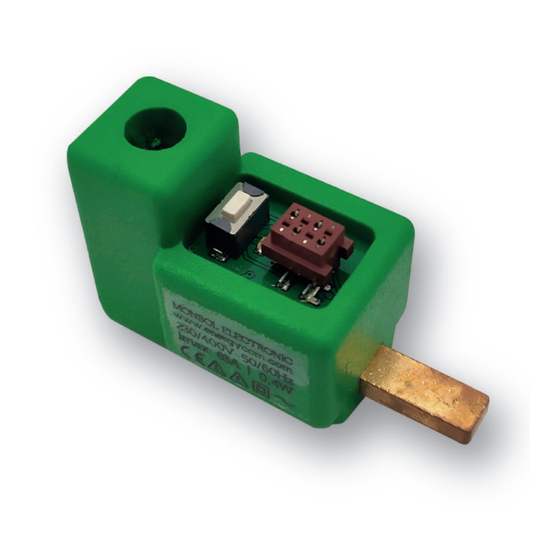
CcM family device must first read and understand this user manual, especially the safety recommendations. In Figure 1 the CcM1-DC is depicted. 3.10 GENERAL SAFETY REQUIRE- MENTS Operator The person in charge of handling the electrical device is responsible for the safety of persons and property. -
Page 8: Identification
• LED: This is a status LED that indicates opera- ting mode of the device. To install CcM1-DC follow these steps: • PUSH BUTTON: A push button to interact with the device. 5.1 STEP 1: SAFETY •... -
Page 9: Step 3: Connection Of The Cables To Ccm1-Dc
5.4 STEP 4: CONNECTION OF CCM1-DC TO THE SWITCH Once the electric cable is inserted in the cable through-hole of the CcM1-DC, connect it to the pro- tection device by inserting the comb in the output current cable through-hole and tighten the bolt of the switch until it is held properly and connects to electricity (Figure 8). - Page 10 Failure to meet tor installed at the secondary bus input of the CcM1- this requirement could produce a short DC device. circuit between the signals that travel through the bus resulting in damage to the connected device. CcM1-DC Manual 2021...
-
Page 11: Operation
6.1.1 Reading mode to in section 4. It is the default mode. The CcM1-DC is taking snaps- An external power supply source of 12 V will be nee- hot measures and the LED flashes twice every 10 ded to power the CcM1-DC connecting VDC and seconds to indicate that everything works correctly. -
Page 12: Communication
(255) will be sent. The communication with the CcM1-DC device will by default take place using the communication If you select the Reset mode of the CcM1-DC, the port RS-485 described above. device will go back to the default Modbus address “1”. -
Page 13: Memory Map
7. MEMORY MAP ID AND MEASUREMENT REGISTERS Modbus Description Length Type Unit register Product identification code DC current Arms x 100 Modbus ID Serial Number Table 2 CcM1-DC memory map CcM1-DC Manual 2021... - Page 14 Calle Elena Soriano, 7 CP: 29006 – Málaga, Spain Tlf: (+34) 952 02 05 80 info@clicmonitor.com | clicmonitor.com...
Need help?
Do you have a question about the CcM1-DC and is the answer not in the manual?
Questions and answers