Table of Contents
Advertisement
Quick Links
273 Branchport Avenue
Long Branch, NJ 07740
(800) 631-2148
www.coopernotification.com
Use this product according to this instruction manual. Please keep this instruction manual for future reference.
MODEL NUMBERS:
SP4-RMX
109919
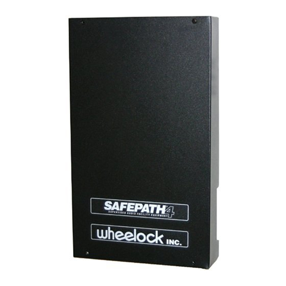
Remote Microphone Expansion Module
:
GENERAL
The SP4-RMX is an outboard expansion module for use with the Safepath system. It is used to expand the number of optional
Remote Microphones (SPRM or SPRM-GP) to three. The PCB assembly is mounted in an enclosure.
READ THESE INSTRUCTIONS CAREFULLY BEFORE USING THIS PRODUCT.
NOTE: All CAUTIONS and WARNINGS are identified by the symbol
Copyright 2009 Cooper Wheelock Inc., dba Cooper Notification. All rights reserved.
Thank you for using our products.
INSTALLATION INSTRUCTIONS
REMOTE MICROPHONE EXPANSION MODULE
Audio Out
SP40S
Panel
Aux In
24VDC
MIC #1
Audio Out
SP4-RMX
MIC #2
Aux In
MIC #3
24VDC
MIC #1
Audio Out
SP4-RMX
MIC #2
MIC #3
Basic Capabilities of the SP4-RMX
. All warnings are printed in bold capital letters.
Audio
Booster
SPB
Aux In
24VDC
Audio Out
*
SP4-RMX
MIC #1
Aux In
*
MIC #2
*
MIC #3
*
These Remote Mics must be SPRM-GP
(General Page Remote Mic). They are NOT
to be used for emergency paging.
Figure 1:
To Speakers
P84557 F
Sheet 1 of 14
Advertisement
Table of Contents

Summary of Contents for Cooper Notification SP4-RMX
- Page 1 Remote Microphone Expansion Module GENERAL The SP4-RMX is an outboard expansion module for use with the Safepath system. It is used to expand the number of optional Remote Microphones (SPRM or SPRM-GP) to three. The PCB assembly is mounted in an enclosure.
-
Page 2: Technical Specifications
Two SP4-RMX modules can be ganged together when connecting them to an SP40S panel. This provides a maximum of six remote microphones providing “All Call” for the entire system. One SP4-RMX can be connected to each audio booster providing three non- alarm/general page remote microphones for that audio booster audio output. - Page 3 Handle the board by its edges, and be careful not to twist or flex it. Install the SP4-RMX in a static free area and the user is to properly attach grounded wrist straps before touching any static sensitive areas.
-
Page 4: Wiring Guidelines
Use shielded twisted pair wire for all audio input and output wiring. Follow national and local regulations for conduit use. The shield of each cable should be connected only at one end. Each shield of each cable that connects to the SP4-RMX is to connect to the grounding terminal provided near the right edge of the chassis (see Figure 2). - Page 5 CONDUIT KNOCKOUTS 2 PLACES, BOTH ENDS 6.00" MOUNTING HOLES GROUND TERMINALS 11.00" MOUNTING HOLES Figure 2: SP4-RMX Mounting NOTE: Drawing is not to scale. P84557 F Sheet 5 of 14...
- Page 6 Figure 3: Wiring Diagram with up to 3 Remote Microphones to an SP40S NOTE: If the SP4-RMX is configured for less than 3 Remote Microphones, the DIP switch for the unused Remote Microphone port (SW3) must be turned OFF. NOTE: When the RMX is connected in SP40S mode, all wiring to and from the SP4-RMX are Power Limited.
- Page 7 • Set SW6 to the contact closure (CC) position. • Remove jumper JP4 to enable supervision of the CC input wiring. Set switches and jumpers on the SP4-RMX as follows • Set SW1 to the SP40 position. • Set Jumper J1 to 1V.
- Page 8 ALL CONNECTIONS BETWEEN SPB AND RMX ARE SUPERVISED. THESE CONNECTIONS MUST BE RUN IN NO MORE THAN 20FT OF CONDUIT AND WITHIN THE SAME ROOM. Figure 5: SP4-RMX Connections Diagram When Using an SPB P84557 F Sheet 8 of 14...
- Page 9 The SP4-RMX is connected to the Audio Booster when the SPB is in the 4-wire mode. The 25V or 70V audio output of the SP40S is wired to the AUX IN on the SP4-RMX. The AUD OUT of the SP4-RMX is then wired to the AUDIO IN on the SPB.
-
Page 10: Operation
When the SP4-RMX is used to expand the remote microphone modules for the SP40S, it is connected to the AUX IN on the SP40S. The priority selection of the remote microphone modules will be after the SP40S onboard microphone (Priority 1). The priorities of the SPRM modules of a second SP4-RMX gang connected to the first will follow the priorities of the SPRM modules connected to the first SP4-RMX. -
Page 11: Emergency Use
NR, TEL, BGM When the SP4-RMX is used for connecting SPRM modules to any of the SPB audio booster modules, the SP40S AUDIO OUT is connected to the SP4-RMX AUX IN and the SP4-RMX AUDIO OUT is connected to the SPB AUDIO IN. This means that the priority level of the SPRM-GP modules are after the digital voice messages on the SP40S and are considered non-alarm conditions. -
Page 12: Troubleshooting
SP40S. LED trouble indication on the system when the SP4-RMX is connected to it. The system TRB LED indicator and D44 AUX IN LED indicator on the SP40S will illuminate when the SP4-RMX has a trouble condition. - Page 13 Figure 6: SP4-RMX PC Board Layout P84557 F Sheet 13 of 14...
-
Page 14: Limited Warranty
LIMITED WARRANTY Cooper Wheelock, Inc. dba Cooper Notification and Cooper Notification, Inc. (each, a “Seller”) products must be used within their published specifications and must be PROPERLY specified, applied, installed, operated, maintained and operationally tested in accordance with these instructions at the time of installation and at least twice a year or more often and in accordance with local, state and federal codes, regulations and laws.

Need help?
Do you have a question about the SP4-RMX and is the answer not in the manual?
Questions and answers