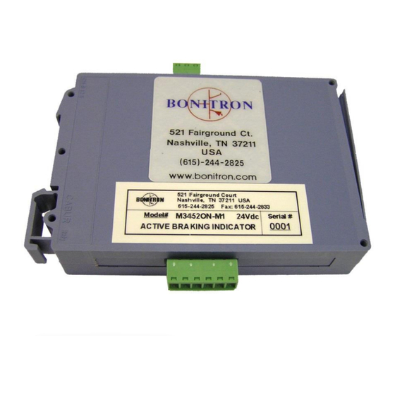
Summary of Contents for bonitron M3452ON
- Page 1 Model M3452ON Active Braking Indicator Customer Reference Manual ● ● Web: www.bonitron.com Tel: 615-244-2825 Email: info@bonitron.com...
- Page 2 Bonitron has seen thousands of products engineered since 1962 and welcomes custom applications. With engineering, production, and testing all in the same facility, Bonitron is able to ensure its products are of the utmost quality and ready to be applied to your application.
- Page 3 RIVE PTIONS In 1975, Bonitron began working with AC inverter drive specialists at synthetic fiber plants to develop speed control systems that could be interfaced with their plant process computers. Ever since, Bonitron has developed AC drive options that solve application issues associated with modern AC variable frequency drives and aid in reducing drive faults.
- Page 4 M3452ON This page intentionally left blank...
-
Page 5: Table Of Contents
Test Mode (Position 9) ........................16 Figure 4-1: Front View ..........................17 5. M ................19 AINTENANCE AND ROUBLESHOOTING 5.1. Troubleshooting .......................... 19 6. E ........................21 NGINEERING 6.1. Dimensions and Mechanical Drawings ..................21 Figure 6-1: M3452ON Chassis Dimensional Outline Drawing ..............21... - Page 6 M3452ON This page intentionally left blank...
-
Page 7: Introduction
1.2. URPOSE AND COPE This manual is a user’s guide for the Model M3452ON Active Braking Indicator. It will provide the user with the necessary information to successfully install, integrate, and use the M3452ON. In the event of any conflict between this document and any publication and/or documentation related to the system, the latter shall have precedence. - Page 8 M3452ON This page intentionally left blank...
-
Page 9: Roduct Escription
RODUCT ESCRIPTION The M3452ON Active Braking Indicator has been designed for use with the M3452 high current braking chopper series. It is intended to provide a contact that may be used to indicate braking activity. The M3452ON module is intended to connect to the Master/Slave control signal of the standard braking modules and provide a Form C MOSFET output isolated from the input. -
Page 10: General Precautions And Safety Warnings
M3452ON 2.4. ENERAL RECAUTIONS AND AFETY ARNINGS H I G H V O L T A G E S M A Y B E P R E S E N T F AI L U R E H E E D... -
Page 11: Installation Instructions
Table 3-1. Wire types and sizes should be chosen in accordance with national and local electrical codes to meet the voltage and current levels present for your application. Figure 3-1 shows a typical interconnection of the M3452ON with a typical braking chopper and I/O signals. -
Page 12: Power Wiring
M3452ON Figure 3-1: Typical Interconnection Diagram MASTER / SLAVE SIGNAL FROM M3452 BRAKING UNIT INPUT SIGNAL ACTIVE LED M3452ON-M1 ACTIVE BRAKING INDICATOR POWER LED OUTPUT PULSE WIDTH SELECT POWER ACTIVE 24Vdc CONTACTS NO C NC Only qualified electricians should perform and maintain the interconnection wiring of this product. - Page 13 User’s Manual Table 3-1: Wiring Specifications LECTRICAL ERMINAL UNCTION ORQUE PECIFICATIONS TB1-1 Signal Input + 0-30VDC to TB1-3 .22-.25 Nm TB1-2 No Connection TB1-3 Signal Input - Common to TB1-1 .22-.25 Nm TB2-1 Power Input + +24VDC to TB2-2 .22-.25 Nm TB2-2 Power Input - 24VDC common to TB2-1...
- Page 14 M3452ON This page intentionally left blank...
-
Page 15: Operation
4.1. UNCTIONAL ESCRIPTION The M3452ON Module monitors the signal from the standard M3452 Braking Transistor module and provides isolated output contacts that follow the input. The output pulse width may be adjusted for longer on-state periods for use by other devices. -
Page 16: Test Mode (Position 9)
M3452ON 4.2.3. OSITION Test mode is used to insure the wiring for the output of the module is correct. In test mode, the output will cycle on and off at 1 second intervals regardless of the input. To enter test mode: Remove 24V power from the module. - Page 17 User’s Manual Figure 4-1: Front View SIGNAL Test Point ACTIVE SIGNAL LED POWER LED OUTPUT PULSE SELECTION COMMON Test Point Dwg: 100045 Rev: 20100323...
- Page 18 M3452ON This page intentionally left blank...
-
Page 19: Maintenance And Troubleshooting
If a problem persists after following the steps below, contact the product supplier or your system integrator for assistance. Repairs or modifications to this equipment are to be performed by Bonitron approved personnel only. Any repair or modification to this equipment by personnel not approved by Bonitron will void any warranty remaining on this unit. - Page 20 M3452ON This page intentionally left blank...
-
Page 21: Engineering Data
User’s Manual NGINEERING 6.1. IMENSIONS AND ECHANICAL RAWINGS Figure 6-1: M3452ON Chassis Dimensional Outline Drawing Dwg: 080361 Rev: 20080819... - Page 22 M3452ON NOTES...
- Page 24 D_M3452ON_CMAN_VALL_00b 04/04/2014 521 Fairground Court ● Nashville, TN 37211 ● USA Tel: (615) 244-2825 ● Fax: (615) 244-2833 ● Web: www.bonitron.com ● Email: info@bonitron.com...

Need help?
Do you have a question about the M3452ON and is the answer not in the manual?
Questions and answers