Table of Contents
Advertisement
Quick Links
An ISO 9001-2008 Certified Company
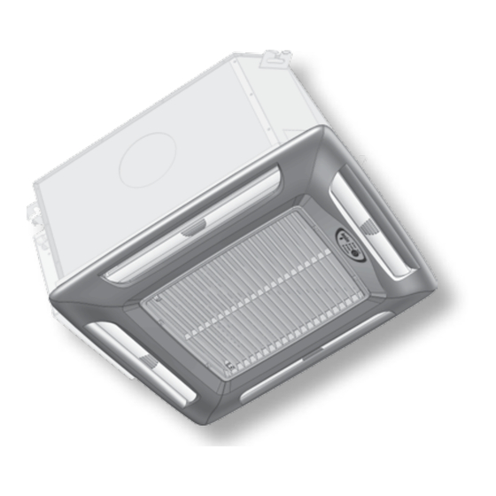
Variable Speed Cassette Ductless
Split System Air Handlers
Straight Cool / Heat Pump Nominal Capacities
CAHV09 CAHV12 CAHV18 CAHV24
9,000
12,000
18,000
2.6
3.5
5.3
8400
8800
17000
2.5
2.6
5.0
Installation, Operation and
Maintenance Manual
ECR International, Inc.
2201 Dwyer Avenue,
Utica NY 13501
web site: www.ecrinternational.com
CAHV
CAHV30 CAHV36 Units
24,000
30,000
35,600
7.0
8.8
10.4
19000
29000
29000
5.6
8.5
8.5
P/N# 240009099, Rev. D [08/06/2013]
Btuh
COOL
kW
Btuh
HEAT
kW
Advertisement
Table of Contents
Troubleshooting

Related Manuals for ECR EMI Ductless CAHV Series

Summary of Contents for ECR EMI Ductless CAHV Series
- Page 1 30,000 35,600 Btuh COOL 10.4 8400 8800 17000 19000 29000 29000 Btuh HEAT Installation, Operation and Maintenance Manual ECR International, Inc. 2201 Dwyer Avenue, Utica NY 13501 web site: www.ecrinternational.com An ISO 9001-2008 Certified Company P/N# 240009099, Rev. D [08/06/2013]...
-
Page 2: Table Of Contents
TAble Of COnTenTS Receiving Information ........................3 Important Safety Information ......................4 General Product Information ......................5 Dimensional/Physical Data ......................6 Installation Considerations ......................8 Mounting The Unit ........................9 Condensate Piping ........................12 Duct Connections ........................13 Refrigerant Piping ........................14 Refrigerant Processing .........................15 Final Assembly ...........................17 Electrical Wiring .........................19 Optional Wired Wall Controller ......................21... -
Page 3: Receiving Information
ReCeIVIng InfORMATIOn Shipping damage MUST be reported to the carrier IMMEDIATELY. Examine exterior. Remove cover and examine compressor and piping for signs of damage. general Information Installation shall be completed by qualified agency. Retain this manual and warranty for future reference. Installer review this manual to verify unit has been installed correctly. -
Page 4: Important Safety Information
IMpoRTAnT SAfETY InfoRMATIon Safety Information All field wiring shall conform to requirements of authority • Installation by qualified personnel. having jurisdiction or in absence of such requirements: • United States - National Electrical Code, ANSI/NFPA 70 • Turn off electrical supply before servicing unit. •... -
Page 5: General Product Information
GEnERAL pRoDUCT InfoRMATIon Standard features CAHV units System Options • Remote or optional wired wall control is required to • Wired wall control. adjust settings and configure controller. • Electric Heat (@ 230v) • When operated by optional wired wall control, controller 1.5 kW —... -
Page 6: Dimensional/Physical Data
DIMEnSIonAL/pHYSICAL DATA figure 1 - Dimensions: Models 9, 12, 18, & 24 (see Table 1, Page 7) Model 9-12 Model 18-24 Features Optional discharge knockouts 5¼-inch diameter (3) available Fresh air inlet knockouts 1¼ x 2½ inches - 9/12 (2) available 3x3 18/24 Model 30-36 Condensate... - Page 7 DIMEnSIonAL/pHYSICAL DATA Table 1 Dimensions — Models 9, 12, & 24 (see figure 1, Page 6) Models 9 & 12 Model 18 & 24 Model 30 & 36 Dimension Inches Inches Inches 25.00 37.00 37.00 25.00 37.00 49.26 1251 22.50 32.44 32.44 2.04...
-
Page 8: Installation Considerations
InSTAllATIOn COnSIDeRATIOnS before Installing Unpacking Cassette fascia and main chassis are packaged together for • Determine best location for mounting unit for room air increased protection. circulation. • Locate outdoor and indoor units as close together as nOTICe possible. • Determine how power wires high and low-voltage, Do not throw template away with packaging. -
Page 9: Mounting The Unit
MoUnTInG THE UnIT Blanking off figure 4 Models 9–12 — One grille & One filter Fascia discharge slot(s) need blanking off when ducts are used to channel conditioned air to other areas. • Position two polystyrene blanking off strips (provided) in fascia discharge slots to direct air to ducts. - Page 10 MoUnTInG THE UnIT Positioning Ceiling Opening Select cassette installation position. nOTICe Pipe work, electrical connections, control box and condensate pump access panels should be readily verify ceiling grid is supported separately from accessible. Refer to cassette dimensions. See Figure 1, the cassette.
- Page 11 MoUnTInG THE UnIT Mounting Method figure 7 - Mounting Brackets • In existing construction, remove enough ceiling panels to provide clearance space for mounting unit to ceiling joists. • Before beginning installation, inspect unit location, test strength of ceiling joists to insure they will support unit weight.
-
Page 12: Condensate Piping
COnDenSATe PIPIng Cassette is supplied with 1/2” I.D. flexible PvC hose for figure 10 - Highest point of Condensate piping connection to copper or plastic drain piping. Should Be As Close To Unit As possible Cassette installation considerations Maximum pump lift is 36” (0.9m) from base or bottom Correct of unit. -
Page 13: Duct Connections
DUCT ConnECTIonS Attach branch duct and fresh air duct collars to cassette figure 12 - Knockouts chassis using following steps. branch Duct knockout Recommend install no more than 10 feet (3m) of branch duct or fresh air duct. Cassette 9-12 Locate knock-out holes. -
Page 14: Refrigerant Piping
RefRIgeRAnT PIPIng Piping Preparation figure 14 - piping Connections At Unit • Avoid piping on wet and rainy days. • Use only clean, refrigeration-grade copper tubing. • Use tubing benders to guard against kinking. • verify no burrs remain on fittings. •... -
Page 15: Refrigerant Processing
RefRIgeRAnT PROCeSSIng Charging Unit figure 18 - Manifold Set Connections At Unit Attach manifold set, vacuum pump, & micron Gauge. See Figure 18. HIGH PRESSURE Evacuate line to 500 microns or less to insure all moisture has been removed and there are no leaks. LOW PRESSURE See Figure 19. - Page 16 RefRIgeRAnT PROCeSSIng Use following example to find charge adjustment and system charge for any air handles and tubing length. Line Adjustment = (Line Charge/FT) x Line Length System Total = Factory Charge + Line Adjustment Round to nearest ounce and allow for gauges and hoses. Table 6 - S1CV / S1HV R410A Refrigerant Charge Table Condenser Cassette...
-
Page 17: Final Assembly
fInAL ASSEMBLY Assembly Instructions figure 22 - Mounting bolts To install the four fascia mounting bolts: Locate supplied bolts and washers from kit bag. Place washers on bolts. Screw mounting bolt with washer into chassis leaving approximately 1” (25mm) to hang fascia. Insure white panel fasteners holding fascia polystyrene are pushed firmly in, fasteners may have loosened in transit. - Page 18 fInAL ASSEMBLY figure 25 - Connect Vane Motor Plug Into figure 27 - Secure fascia To Chassis Socket on Chassis Female vane motor plug on chassis Do not over-tighten bolts could damage fascia and drain pan. figure 28 - Adjust louver Position 30° from Plumb Male vane Motor Plug On Fascia figure 26 - Connect Infrared Unit Cable...
-
Page 19: Electrical Wiring
eleCTRICAl WIRIng general electrical Requirements figure 29 - Remove Control box Cover Electrical wiring must be in accordance with all electrical codes. In absence of such requirements to the National Electrical Code (NEC). WARnIng Electrical shock hazard. Turn OFF electrical power supply before making electrical connections. - Page 20 eleCTRICAl WIRIng Low-Voltage Electrical Wiring figure 31 - Unit-Mounted Controls — Cooling Only Low-voltage interconnect wiring must be 18 AWG. Locate 24v control transformer in air handler. Provides low-voltage control power to both air handler and condenser. Low-voltage interconnect control wiring may vary depending on model selected.
-
Page 21: Optional Wired Wall Controller
OPTIOnAl WIReD WAll COnTROlleR Optional Controller eMI Wired control EMI offers wired wall control compatible with EMI split sys- tem air handlers for variable speed condensers. fan Operation Controls call for fan operation (On or Off). After controller has been satisfied and call for heating or cooling has been removed, indoor fan remains on for ad- ditional 60 seconds. -
Page 22: Optional (Cahv) Wired Wall Controller Operation
OPTIOnAl (CAHV) WIReD WAll COnTROlleR OPeRATIOn Wall Mounted Control Configuration Wall mounted control layout, see Figure 34 and Figure 35. Low voltage interconnect wiring must be at least 18 AWG. 24v control transformer is located in air handler unit. Provides low volt control power to both air handler and condenser. - Page 23 OPTIOnAl (CAHV) WIReD WAll COnTROlleR OPeRATIOn A/C Condenser With Electric Heat operation nOTICe Configure wired wall controller operation with optional elec- tric heat control - Heat Source ON. Once cooling has cycled off or following power outage, compressor will not start for at least three Wired Wall controller’s call for electric heat operation - (On (3) minutes (short-cycle protection).
-
Page 24: Initial Start-Up - Cahv Units
InITIAL START-Up — CAHV UnITS WARnIng Electrical shock hazard. Turn off power to indoor and outdoor units before proceeding. Failure to follow these instructions could result in death or serious injury. CAHV Units • Set controller functions before proceeding with start-up. •... - Page 25 InITIAL START-Up — CAHV UnITS WARnIng figure 36 - Checking Condensate pump Operation Electrical shock hazard. Turn off power to indoor and outdoor units before proceeding. Failure to follow these instructions could result in death or serious injury. Remove adjacent ceiling tile to access condensate pump cover panel.
- Page 26 InITIAL START-Up — CAHV UnITS Verify Compressor Operation — All Systems WARnIng Place system controls into cooling mode, with setpoint Electrical shock hazard. Turn off power to indoor and below room temperature. outdoor units before proceeding. Failure to follow verify compressor start up, noise, vibration, and overall these instructions could result in death or serious system operation.
- Page 27 InITIAL START-Up — CAHV UnITS Verify Heat Pump Operation - No Electric Heat This is heat pump outdoor unit with no heat source in Cassette (indoor) unit. Set configuration for Heat Source OFF, Heat Pump ON. See Figure 42, Page 32. Use remote to set MODE to Cool.
-
Page 28: Cahv Controller Overview
CAHV COnTROlleR OVeRVIeW WARnIng figure 37 - EMI Unit Mounted Controller Control Panel Electrical shock hazard. verify all power is off from both indoor cassette unit and outdoor condenser unit before removing control box cover. Failure to follow these instructions could result in death or serious injury. - Page 29 CAHV COnTROlleR OVeRVIeW figure 38 - Unit-Mounted Receiver — Chassis-Mounted Display Infrared Receiver Window power LED Wired Wall Controller mode — on when power is applied to unit. Infrared Controller mode — on while cassette unit is in ON mode; off while unit is in OFF mode.
- Page 30 CAHV COnTROlleR OVeRVIeW fIGURE 39 - CAHV Microprocessor Controller — Infrared Remote Control Press to turn unit ON or OFF. Press and hold 2 seconds to transmit all settings POWeR to unit-mounted controller. Press to toggle through operating modes — Heat, Cool, Auto Changeover, Dry MODe or Fan.
-
Page 31: Wired Wall Controller Configuration
WIRED WALL ConTRoL ConfIGURATIon figure 40 - Wired Wall Control Operation Wired Controller button Selections POWER Press to turn unit on or off. MODE Press to toggle through operating modes — Cool, Dry, Fan, Heat or Auto Changeover Normal operation — hold 3 seconds to enter Set Time mode; hold again 3 seconds to exit. In programming mode CLOCK —... - Page 32 WIRED WALL ConTRoL ConfIGURATIon figure 41 - 7-Day Programming Options for CAHV Item Setting Values overview To access: Press and hold PROGRAM and CLOCK buttons simultaneously 3 seconds; use arrow keys to select position; save selection and exit by repeating button press. Quick copy —...
-
Page 33: Setting The Controller
SeTTIng THe COnTROlleR figure 42 - Configuration Mode for CAHV Air Handlers Possible Value factory Item Display overview (flashing) Settings To access: Press MODE and PROG together 5 seconds, repeat to exit; automatically exits after 20 seconds idle Fahrenheit Temperature Setting 01 F-C Select temperature scale for display and operating settings. - Page 34 SeTTIng THe COnTROlleR Table 7 programming Schedule (When Using 7-Day programming) To copy the settings from any day to the entire week: Select the day to be copied. Simultaneously press the “FaN” and “PROg” buttons for three seconds.
-
Page 35: Hand Held Controller Operation
HAnD HelD COnTROlleR OPeRATIOn power When power is first applied to control or after power outage there is three (3) minute delay before compressor or Pressing POWER button momentarily switches unit either electric heat will energize. Protects unit from short cycling on or off. - Page 36 HAnD HelD COnTROlleR OPeRATIOn Cooling Mode optional Heat pump Without Electric Heat (Heat pump Unit outdoors) For cooling operation, turn unit on via POWER button. EMI heat pumps are intended to operate with indoor air Select Cooling mode via MODE button. handler, with optional electric heat.
- Page 37 HAnD HelD COnTROlleR OPeRATIOn When room temperature has been satisfied for at least • Should room temperature fall below setpoint sixty (60) seconds and two (2) minute minimum on- temperature by 2 degrees, compressor stops and time has elapsed, compressor switches off. heating continues to boost room temperature back up to setpoint temperature.
- Page 38 HAnD HelD COnTROlleR OPeRATIOn three (3) seconds. settings. Pressing PROGRAM button advances to next item. Setpoint and time settings are programmed into control Order is (1) Day of week, (2) Hour and (3) Minute. through 7-Day Programming mode. Time of day and day of week are changed using UP or Pre-Programmed Run mode is entered from Cooling DOWN ARROW buttons.
-
Page 39: Wired Wall Controller Operation
WIReD WAll COnTROlleR OPeRATIOn fan Operation Optional Heat Pump With Electric Heat (Two-Stage Heating) • Cassette unit utilizes 3 speed motor. In wired wall Optional wired wall control controls call for electric heat controller operation, fan speed selection can be made operation (on or off). -
Page 40: Cahv Controller Features
CAHV ConTRoLLER fEATURES Short Cycle protection (ASCT) • Anti-short-cycle timer (ASCT) is designed to protect compressor from short cycling. • ASCT is activated immediately following Off cycle of outdoor unit. Once room temperature is satisfied and outdoor unit switches off, ASCT does not allow outdoor unit to restart unit 3 minute time period has elapsed. - Page 41 CAHV ConTRoLLER fAULT ConDITIonS Table 8 CAHV Microprocessor Controller fault Indications Alarm failure leD- Type/ fault Condition Description number of location flashes Dirty filter Clean filter,press warning/clear filter button Drain pan condensate fault Condensate, check for drain blockage or pump failure EPROM failure Check indoor EPROM Failure for ambient temperature...
-
Page 42: Maintenance
MAInTenAnCe figure 43 Remove grille WARnIng Electrical shock hazard. Before removing access panels, verify all power is disconnected from the Model 12 unit. Failure to follow these instructions could result shown in death or serious injury. Have service performed by a qualified service agency. Annual system check is recommended. -
Page 43: Troubleshooting - General
TRoUBLESHooTInG - GEnERAL WARnIng Electrical shock hazard. Before removing access panels or control covers, verify all power is disconnect all high volt power supplies to both the indoor unit and outdoor unit. Failure to do so could result in injury or electric shock. Wiring Diagram Troubleshooting indoor unit, see wiring diagram(s) supplied with equipment. -
Page 44: Troubleshooting - Cahv Units
TRoUBLESHooTInG - CAHV UnITS Cooling-only Units Low Voltage Controls Optional Heat Pump With Electric Heat Applications • Cooling only units require 18 AWG low-voltage Heat Pump systems utilize 6 low volt interconnecting wires interconnecting wires between indoor and outdoor between indoor, and outdoor. units. - Page 45 TRoUBLESHooTInG - CAHV UnITS Heating Indoor unit contains electronic anti-short-cycle timer feature (ASCT) which prevents outdoor condenser from Two Stage Heating short cycling. Heat pump units accommodate two-stage heating when After control is satisfied there is a three (3) minute delay optional electric heater is present in combination with heat before condenser is allowed to restart.
- Page 46 TRoUBLESHooTInG - CAHV UnITS Cassette operation can be controlled through optional wired WARnIng wall controller or infrared handheld controller. Electrical shock hazard. Before removing access Heat pump Units, Model CAHV panels, verify all power is disconnected from the Heat pump units require 18 AWG minimum low-voltage unit.
-
Page 47: Frequently Asked Questions
fREQUEnTLY ASKED QUESTIonS Q: Condenser will not start although indoor unit appears • Does system have proper refrigerant charge? System normal. What should I do? low on refrigerant can cause air handlers freeze-up. To A: At indoor control, verify control is in cooling and check system charge you need to contact a qualified setpoint temperature is below room temperature. -
Page 48: Specifications
SPeCIfICATIOnS Table 9 Electrical Specifications CAHV fan Motor elect Heat Total HACR Model M.C.A. AMPS Volt bRKR Volts/HZ/PH H.p. kW AMPS 208/230/60/1 0.35 1/10 – – CAHV09 / 208/230/60/1 0.35 1/10 6.52 CAHV12 208/230/60/1 0.35 1/10 13.04 13.4 16.8 208/230/60/1 0.55 –... -
Page 49: System Performance
SYSTEM pERfoRMAnCE CaHV Cassette(s) S1CV/S1HV Side Discharge Table 12 Cooling Systems CAHV Condenser Cassette Btuh SeeR Ref. S1Cv9000 CAHv09 9,000 15.0 .079 13.0 R410A S1Cv2000 CAHv12 12,000 15.8 0.69 12.0 R410A S1Cv8000 CAHv18 18,000 17.0 0.74 13.0 R410A S1Cv4000 CAHv24 24,000 17.0 0.66... -
Page 50: Test Unit Performance Data Sheet
TEST UnIT pERfoRMAnCE DATA SHEET nOTICe Performance Data sheet provided for use by qualified service professional in event there is concern with unit. Have information ready when calling. Include Model Number, Serial Number, and Date of installation. Technical Support Department @ 1-800-228-9364. Date: Model Number Technician:... - Page 51 notes...
- Page 52 Phone: 1-800-228-9364 2201 Dwyer Avenue, Fax: 1-800-232-9364 Utica NY 13501...