
Summary of Contents for Advanced AxisAX AX-PENN
- Page 1 AX-PENN & AX-PENN/ST7 Peripheral Expansion Network Node Installation & Operation Manual www.advancedco.com...
-
Page 2: Table Of Contents
Table of Contents Page INTRODUCTION / OVERVIEW ..........................3 ............................3 RODUCT ESCRIPTION INSTALLATION ................................. 4 ................................4 OUNTING ................................ 4 IMENSIONS ................................5 IRING 2.3.1 24VDC Power Supply ........................... 6 2.3.1.1 Power Supply Monitoring ............................. 6 2.3.1.2 Intelligent Power Supply Monitoring ........................6 2.3.2 Ad-NeT-PluS Network Connection ....................... -
Page 3: Introduction / Overview
AX-PENN (/ST7) peripheral expansion network node modules provide an on-board Axis AX peripheral bus (PBUS) allowing for the connection of any Advanced peripheral bus module remotely from the Axis AX fire alarm control panel (i.e.: switch LED modules, audio amplifier modules, relays, etc.). -
Page 4: Installation
The AX-PENN (/ST7) is designed for mounting within any Advanced enclosure. The module mounts wherever an Advanced peripheral bus module can be mounted. In addition, the module can be mounted to a single aperture plate for single aperture opening installation (see figure 1 mounting locations). -
Page 5: Wiring
2.3 Wiring The AX-PENN (/ST7) peripheral expansion network node module is designed to be easy to install and wire. Pluggable terminal blocks are provided for all wiring which can accommodate up to 14 AWG wire. Confirm wiring sizes are adequate to deliver the required load current and maintain compatibility with the device voltages. Note: Disconnect all sources of power (AC and battery) before installing components or servicing the module. -
Page 6: 24Vdc Power Supply
2.3.1.2 Intelligent Power Supply Monitoring If the AX-PENN (/ST7) is powered internally by an Advanced AX-PSU-6 power supply charger, connect the supplied 4 pin connecter to the PL2 plug-in connector on the AX-PSU-6; connect the other end of the supplied 4 pin connector to the PSU COM (PL3) plug-in connector on the AX-PENN (/ST7) [see figure 5]. -
Page 7: Ad-Net-Plus Network Connection
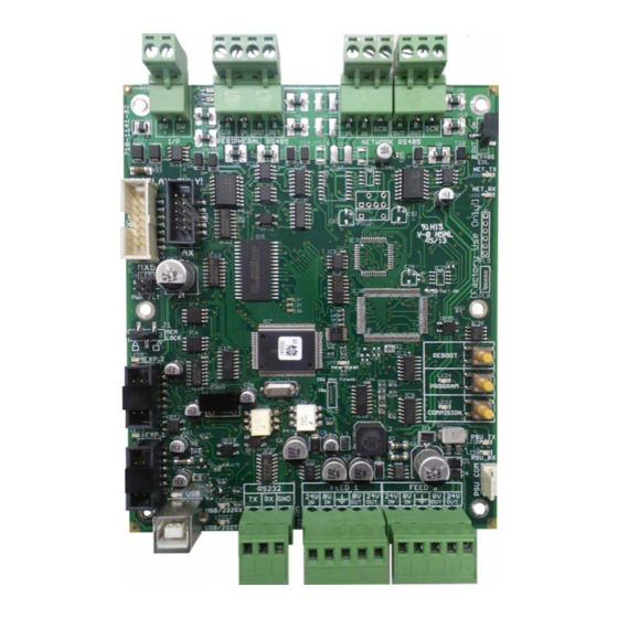
P485 TX P485 RX PERIPHERAL RS485 NETWORK RS485 NET485 NET TX DISPLAY ONLY NET RX PWR FLT FTNET HB LOCK REBOOT HEARTBEAT PROGRAM COMMISION PSU_TX PSU_RX RS232 FEED 1 FEED 2 USB/232RX USB/232TX Figure 5 – Intelligent Power Supply Wiring Figure 6 –... -
Page 8: Ax-Penn (Class B) Ad-Net-Plus Network Wiring
2.3.2.1 AX-PENN (Class B) Ad-NeT-PluS Network Wiring Wire the Ad-NeT-PluS network, A OUT, B OUT and SCN (shield) from the previous node to the A IN, B IN and SCN (shield) terminals of the AX-PENN module (see figure 7). Wire the A OUT, B OUT and SCN (shield) of the AX-PENN module to the next network node. -
Page 9: Class X Ad-Net-Plus Network
2.3.3 Peripheral Bus (P-BUS) The AX-PENN (/ST7) can support sixteen (16) of each type of Advanced peripheral bus modules. Peripheral bus modules must be located within 20 feet of the AX-PENN (/ST7) module within the same room. Below is a list of... -
Page 10: Wiring
Class A communications. 2.3.4 Optional AX-DSP Keyboard Display The AX-PENN (/ST7) can support a standard Advanced AX-DSP keyboard display, simply wire the keyboard display cable to the AX serial port on the AX-PENN (/ST7) [see figure 10]. -
Page 11: Usb Port
The AX-DSP connected to an AX-PENN (/ST7) will offer all the features and benefits it offers on a standard fire alarm control panel; including the three (3) programmable function buttons, six (6) programmable function LEDs and eight (8) programmable switch inputs located on the back of the display. 2.3.5 USB Port The AX-PENN (/ST7) incorporates a USB port for PC-NeT upload/download programming (see figure 11). -
Page 12: Ax-Penn (/St7) Pc-Net Programming
3 AX-PENN (/ST7) PC-NeT Programming Adding an AX-PENN (/ST7) Network Node Within the AxisAX Series Configuration Software 6.81 or higher, after installing an AxisAX panel , click on the add product icon and select the AxisAX-PENN network peripheral. Rename If you would like, rename the AX-PENN from Panel 2 to an appropriate name and click OK , which will add the AX-PENN (/ST7) to the installation. -
Page 13: Panel Details Programming
Once the AX-PENN has been added to the installation, the user will need to program the AX-PENN Panel Details. In addition to the AX-PENN Panel Details programming, the AX-PENN will also require On-Board, User Interface and Peripheral Bus programming. 3.1.1 Panel Details Programming Within the Panel Details area of the AX-PENN, the user will need to review and if required, modify the defaulted Panel Details programming for General, Display Options, Service Options, Disable Output Menu Options, Daylight Saving Settings, Trouble Notification and Printer options (see below). -
Page 14: On-Board Programming
3.1.2 On-Board Programming The On-Board programming area of the AX-PENN allows the user to utilize and define the eight (8) programmable switch inputs of the optional AX-DSP keyboard display, the switch input (I/P SW+ and SW-) of the AX-PENN and the AC trouble monitoring of an associated AX-PSU-6, if intelligently connected. -
Page 15: Peripheral Bus Programming
3.1.4 Peripheral Bus Programming The Peripheral Bus programming area of the AX-PENN is where the user adds and programs the AX-PENN associated peripheral bus (PBUS) modules. Uploading, Downloading and Firmware Flashing There are three (3) buttons and two (2) LEDs associated with the AX-PENN (/ST7) PCB (printed circuit board) for use in uploading, downloading and flashing an AX-PENN (/ST7) REBOOT module. -
Page 16: Uploading And Downloading Procedure
To update AX-PENN (/ST7) firmware: 1. Attach your PC (personal computer) to the USB port of the AX-PENN (ST7) and REBOOT open the Advanced Flasher Program. 2. Press and hold the PROGRAM button. 3. Press the REBOOT button, the associated PROGRAM LED will illuminate. -
Page 17: Axis Ax Wiring Guide
The SLC circuits are capable of driving high current loads in alarm, which affects the load characteristics including V/I drops along the wire length. Therefore, it is important to utilize Advanced loop calculator in determining wire gauge and length. Twisted Shielded Pair... - Page 18 Typica Circuit Maximum l Wire Circuit Type Wire Types Comments Function Distance Size (AWG) IDCs SLC based Untwisted Unshielded, 300 feet 18-20 EOL resistor value varies depending upon module. (power limited) initiating Twisted Pair or Twisted device input Shielded Pair. circuits &...
- Page 19 Examples: Number of Firefighter Jacks/Phones Max Cable Resistance (ohms) www.advancedco.com...
-
Page 20: Ax-Penn (/St7) Status Leds
5 AX-PENN (/ST7) Status LEDs P485 TX P485 RX PERIPHERAL RS485 NETWORK RS485 NET485 NET TX DISPLAY ONLY NET RX PWR FLT FTNET HB LOCK REBOOT HEARTBEAT PROGRAM COMMISION PSU_TX PSU_RX RS232 FEED 1 FEED 2 USB/232RX USB/232TX LED Function Description Heartbeat LED Normal: Flashes at 1Hz... - Page 21 www.advancedco.com...
- Page 22 Doc Number: 682-059 AFS Revision: 100 South Street, Hopkinton, Massachusetts 01748 Tel: (508) 435-9995 Fax: (508) 435-9990 First Issued: 2013-mm-dd Email: usa@advancedco.com Web: www.advancedco.com www.advancedco.com...
Need help?
Do you have a question about the AxisAX AX-PENN and is the answer not in the manual?
Questions and answers