Table of Contents
Advertisement
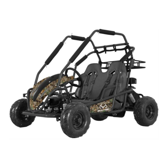
Model RTK200
Assembly Instructions
PLEASE NOTE THAT THIS IS NOT THE OWNER'S MANUAL BUT THE
ASSEMBLY INSTRUCTIONS ONLY.
BEFORE OPERATING THIS GO-KART, MAKE SURE THE OPERATOR AND
PASSENGER HAVE READ AND UNDER STAND THE OWNER'S MANUAL,
WARNING LABELS AND ARE FAMILIAR WITH ALL GO-KART CONTROLS.
FOR QUESTIONS REGARDING ASSEMBLY OF THIS GO-KART, PLEASE CALL
COLEMAN POWERSPORTS, TOLL FREE 888-405-8725
colemanpowersportsusa.com
REV052720
Advertisement
Table of Contents

Summary of Contents for Realtree RTK200
- Page 1 Model RTK200 Assembly Instructions PLEASE NOTE THAT THIS IS NOT THE OWNER'S MANUAL BUT THE ASSEMBLY INSTRUCTIONS ONLY. BEFORE OPERATING THIS GO-KART, MAKE SURE THE OPERATOR AND PASSENGER HAVE READ AND UNDER STAND THE OWNER'S MANUAL, WARNING LABELS AND ARE FAMILIAR WITH ALL GO-KART CONTROLS.
-
Page 2: Removal From Crate
REMOVAL FROM CRATE 1. Remove the metal crate Wheel Parts from the Go-Kart. 2. Locate and Remove Owner’s/Operator’s manual, set up instructions and all documentation. Rear Tires Note: Read Owner’s / Operator’s manual thoroughly before starting Go-Kart for the first time. 3. - Page 3 Brush Guard Parts Main Brush Guard Brush Guard Cross Braces Brush Guard Side Support Safety Belt Seat Safety Net...
-
Page 4: Rear Wheel Assembly
REAR WHEEL ASSEMBLY Hardware: M20 Washer 2ea. (1) M20 Castle nuts 2ea. (2) Cotter pins 2ea. (3) 2ea. (4) M20 Large Washer 1.Lift the Kart with a jack. Note: Make sure tire tread faces forward and Air valve stem is on the outside of the tire when installing. -
Page 5: Front Wheel Assembly
FRONT WHEEL ASSEMBLY Hardware: M14 Washer 2ea. (1) M14 Castle nuts 2ea. (2) 2ea. (3) Cotter pins M14 Large 2ea. (4) Washer 1. Lift the Kart with a jack. Make sure tread faces forward 2. Install the front wheel assembly in the following order. -
Page 6: Steering Wheel Installation
STEERING WHEEL INSTALLATION Hardware: M6X16 Bolts 3ea.(1) M6 Nuts 3ea.(2) 1. Attach steering wheel using M6 bolts (1) and M6 nuts (2). 2. Attach steering wheel cap by snapping into place on center of steering wheel. Steeling Wheel... -
Page 7: Seat Installation
SEAT INSTALLATION Hardware: M8 x 35 bolts 2 ea. (1) M8 Nuts 2 ea. (2) 1. To install the seat, attach the barb, located on the bottom of the seat, to the barb bracket on the Go Kart before attaching the bolt. 2. - Page 8 BRUSH GUARD INSTALLATION Hardware: M8 X bolts 4 ea. (1) M8 X 20 bolts 12ea. (2) M8 Concave Washers 4 ea. (3) 1.Attach Main Brush Guard withM8x20 bolts. Note:Do not tighten bolts at this time,keep bolts loose until the brush guard is completely assembled.
- Page 9 REAR SAFETY NET 1.Attach safety net on brushguard.
- Page 10 REAR RACK INSTALLATION Hardware: M8x16 bolts ea.(1) M8 nuts 4 ea. (2) Assemble the rear rack to the roll mounting point with Flange bolt M8x16(1)and nut M8.
-
Page 11: Pre-Ride Inspection
PRE-RIDE INSPECTION Inspecting and checking the WHAT TO CHECK FOR CHECK condition of the Go Kart before each ride is important. Steering • Smoothness • No restriction of Following the pre-ride check movement list will help insure the you do Brakes •... - Page 12 WARNING Never Attempt to start this Go-Kart without reading and understanding the Owner’s/Operator’s manual. The Owner’s/Operator’s manual provides information on safety, parts, functions, pre-ride inspection, starting and maintenance. Coleman Powersports Phone: 888-405-8725 Colemanpowersportsusa.com...
Need help?
Do you have a question about the RTK200 and is the answer not in the manual?
Questions and answers