
Summary of Contents for Scanivalve ECM4000
- Page 1 ECM4000 Ethernet Control Module Hardware and Software Manual Software Version 1.01...
-
Page 4: Preface
Warranty not to be defective, shall be at the expense of Buyer or the end user, whomever has returned such product or compo- Scanivalve Corporation, Liberty Lake, Washington, nent part. hereafter referred to as Seller, warrants to the Buyer and the first end user that its products will be free from... -
Page 5: Trademarks ® And Copyrights
Packaging for Shipment If the product must be shipped, whether being returned to Scanivalve or relocated to another location, it must be packaged properly to minimize the risk of damage. The recommended method of packing is to place the instru-... - Page 6 [INTENTIONALLY LEFT BLANK]...
-
Page 7: Table Of Contents
Setting Up an Ethernet Connection Using a Static IPv4 address Using a Dynamic IPv4 address Using an IPv6 address Changing the IP Address Pneumatic Interface Interfacing with Scanivalve Scanners Digital Inputs/Outputs Digital Outputs Digital Inputs Status LEDs Scripts Creating Scripts... - Page 8 Table of Contents ECM4000 Syntax Errors Time-out Errors Warning and Error Routing IEEE1588v2 Precision Time Protocol Device Monitor (DMON) Web Server Web Server: Main Display Web Server: Home Web Server: Setup Web Server: File Browser Web Server: Error Log Section 4: Hardware...
- Page 9 Set PTP Statistical Output Set UTC Offset General Configuration Variables (LIST CONFIG) Debug Configuration Return Prompt Configuration AutoRun ECM4000 Name Script Error Action Device Configuration Variables (LIST DEVICE) Device Configuration Digital Event Configuration Variables (LIST DEVENT) Digital Event Configuration CALZ Configuration Variables (LIST CALZ)
- Page 10 Table of Contents ECM4000 DMON Remove State DMON Modify State Bit Pattern DMON Monitor Timeout DMON Poll Section 6: Maintenance Firmware Installation (Windows 7, 8, 10) Firmware Installation via Web Server Firmware Installation via Serial Codeskin Installation DIP Switch Access...
- Page 11 Section 1: Specifications Section 1: Introduction ECM4000 ECM4000 [INTENTIONALLY LEFT BLANK]...
-
Page 12: Section 1: Specifications
[168.3mm x 54.6mm x 204.1mm] -40°C to 70°C with Heater Storage 0 to 80°C Weight ECM4000 2.31lbs [1.05kg] Humidity ECM4000 with Heater 2.43lbs [1.10kg] Operation 5 to 95% RH, Non-Condensing Storage 5 to 95% RH, Non-Condensing Supply Air Input Fitting 1/4” Swagelok... - Page 13 Section 1: Specifications Section 1: Introduction ECM4000 ECM4000...
-
Page 14: Section 2: Introduction
ECM4000’s IEEE1588 synchro- to be configured as a PTP salve when a PTP Grandmaster nization. is present on a network. Alternatively, the ECM may be configured to act as a PTP master in a Scanivalve system 81363-1 NOTES: REMOTE CONTROL PANEL... -
Page 15: Ecm Front Panel
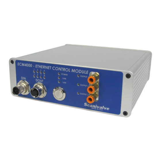
Section 2: Introduction ECM4000 ECM Front Panel The ECM’s front panel houses several different interfaces and indicators. Power, Ethernet, and Pneumatic Output Activity Indicator LEDs Indicator LEDs Status LEDs Digital Input Pneumatic (DIN) Connector Digital Output Power On/Off Outputs (DOUT) Connector... - Page 16 Section 2: Introduction ECM4000 [INTENTIONALLY LEFT BLANK]...
-
Page 17: Section 3: Operation
A stainless steel mounting strap will is provided with the cations with the module for cases in which an Ethernet ECM4000 to allow the module to be mounted in a perma- connection cannot be established. If the internal memory nent location. The mounting straps tabs are approximately of the ECM becomes corrupted, the serial connection 0.050”... -
Page 18: Serial Communications
DHCP server present. Serial Communications Every ECM4000 module has an serial connector. It is avail- Using a Static IPv4 address able through the ‘Serial’ connector on the back panel of the module. -
Page 19: Using A Dynamic Ipv4 Address
This feature is not currently active. Using a dynamic IPv4 address will be enabled in a future software update. The ECM4000 can be setup to have a IP address dynami- cally assigned from a DNS server using DHCP. When the IP address is set to 0.0.0.0, DHCP is used. -
Page 20: Using An Ipv6 Address
ScanTel is a free communications utility designed by Scani- valve to communicate with Scanivalve products including the ECM4000. It is a text based, command line program that allows users to connect to a single ECM module. ScanTel can be downloaded from the Scanivalve website. -
Page 21: Pneumatic Interface
Section 3: Operation ECM4000 - or - Cycle the ECM power. The ECM4000 has 8 digital outputs and 8 digital inputs that The ECM will now boot with the new IP address. can be configured to perform a number of duties. -
Page 22: Status Leds
Status LEDs A double slash // can be used anywhere in a script file to The ECM4000 has 8 status LED indicators on the front panel denote comments. The ECM will not process any characters that can be independently controlled. Each of the status that proceed a double slash. -
Page 23: Pre-Programmed Scripts
If TOSTOP == 0, the script will continue through the error and write the error to the error log. TCP/IP Commands - or - A unique feature of the ECM4000 is the ability to send • If TOSTOP == 1, the script is stopped and the error... -
Page 24: Time-Out Errors
“state,” the ECM will confirm that all • Enabled as a PTP master device. enabled devices match the same state and set the digital outputs according to the configured “state.” When the ECM4000 is configured as a PTP slave device (SET... - Page 25 DMON will update to the Examples of DMON configuration and uses with other current matched state. Scanivalve devices can be found in Appendix A of the • If devices do not match the same configured state manual.
-
Page 26: Web Server
Microsoft Edge Mozilla Firefox To connect to the ECM4000’s Web Server, simply open one of the supported browsers and enter the ECM’s IP address into the address bar. Once connected, the Web Server’s Home screen will be displayed as shown in figure 3-5. -
Page 27: Web Server: Main Display
Section 3: Operation ECM4000 Web Server: Main Display Figure 3-7: Main Display The top portion of the Web Server is the “Main Display.” This display will remain constant through all pages of the Web Server. This display provides a digital representation of the ECM’s front panel and will provide visual indicators for the digital outs, status LEDs, and pneumatic outs. -
Page 28: Web Server: Home
This section provides links that will be directed to different resources on Scanivalve’s website. These pages will provide general information, ECM4000 resources (such as links to the manual or data sheet), and a link to Scanivalve’s contact form. NOTE: These hyperlinks will only work successfully if an internet connection is available. - Page 29 Section 3: Operation ECM4000 Web Server: Home (Cont.) This section provides a “Terminal” emulator screen, allowing the user to send simple text commands to the ECM. While the Web Server pages provide many configurations and commands, not all variables are available in the GUI. The “Terminal”...
-
Page 30: Web Server: Setup
Section 3: Operation ECM4000 Web Server: Setup The Setup page is used for configuring devices, configuring Digital In assignments, and configuring Precision Time Protocol settings. This section displays configured remote devices, allows device properties to be changed, or new devices to be added. - Page 31 Section 3: Operation ECM4000 Web Server: Setup (Cont.) This section will create events to run scripts based on digital input signals. NOTE: This section will only explain the use of the table and will not explain in detail about digital in events.
- Page 32 Section 3: Operation ECM4000 Web Server: Setup (Cont.) This section will control the IEEE-1588v2 Precision Time Protocol variables. PTP ENGINE -- The PTP Engine can be enabled/ disabled by using the three radio buttons: SLAVE -- Will assign the ECM to listen for PTPv2 packets on a network and synchronize with a PTP Grandmaster.
-
Page 33: Web Server: File Browser
If a new filename is entered, a new file will be created and saved. Script file names cannot include spaces and cannot exceed 32 characters in length. Note: Files that do NOT match .cfg, .txt, and ECM4000.hex are considered unsupported and the ECM will not upload these files. - Page 34 Section 3: Operation ECM4000 Web Server: File Browser (Cont.) SCRIPT CONSOLE This window will allow you to view all scripts within a script file and provide the ability to run and stop scripts. The script console tab will only be available when a script file (.txt) is selected and will be the...
-
Page 35: Web Server: Error Log
Section 3: Operation ECM4000 Web Server: Error Log The Error Log page is used to view errors messages stored in the ECM. A red error light will appear at the end of “LOG” whenever errors are listed on this page. The errors will be listed using the same syntax outlined in the ERROR command. - Page 36 Section 4: Hardware ECM4000 [INTENTIONALLY LEFT BLANK]...
-
Page 37: Section 4: Hardware
Scanivalve bulged stainless steel tubulation sizes with the use of internal solenoids. These solenoids can be such as 0.063” OD and 0.125” OD. Please see the Scanivalve activated and deactivated using software commands. The Accessory Catalog for more information on available tubing pressure supplied to the “Supply Input”... -
Page 38: Making Tubing Connections To Push-In Style Fittings
65W max. Figure 4-5 - Power Wiring Ethernet Connector The primary means of communication with the ECM4000 Figure 4-4: Push-In Style Connections module is the 100Base-T Ethernet port with MDIX auto- crossing. The ECM uses a M12, 4-pin, D-Code connector Electrical Connectors for the Ethernet connection. -
Page 39: Digital Out Connector
A 3ft M12 to male RJ45 cable is provided with every ECM4000. Additional Ethernet cables for the ECM4000 modules can be ordered from Scanivalve in any length up to 100 feet (30 meters). Scanivalve’s part number for these cables is 155035. -
Page 40: Serial Connector
Serial Communication cable can be ordered from Scanivalve using Scanivalve part number 155829. The wiring diagram for the RS-232 output is shown in figure 4-10. The cable wiring must connect the Tx output from the host computer to the Rx input of the ECM4000. Also,... - Page 41 Section 5: Software ECM4000 [INTENTIONALLY LEFT BLANK]...
-
Page 42: Section 5: Software
RETURNS lists the format of the information that the unit returns to the host. A PROMPT may be output when the ECM4000 is ready to accept a command. The prompt in the ECM is configurable. This manual shows all returns and examples as if SET PROMPT 1 > is configured. -
Page 43: General Control Commands
General Control Commands Load Script COMMAND LOAD SCRIPT DESCRIPTION The ECM4000 will load the specified script file and make the script file active. When active, scripts within the file can be run. SYNTAX LOAD <script filename> Where: <script filename> - the name of the script file to LOAD and become the active script file that contains the scripts to execute. -
Page 44: Status
SET DEVICE 2 DSA16 ENABLED TIMED-OUT CONNECTED > Version COMMAND VERSION DESCRIPTION Shows the current software version. SYNTAX RETURNS The version followed by the prompt when ready for the next command. VALID MODES READY EXAMPLE ECM Scanivalve (c) 2020 Ver 1.00 >... -
Page 45: Wait
Min value - 1 Max value - 86400 [<option>] - when the option is a device name, the ECM4000 will poll that device for READY mode and use the time in seconds as a maximum wait time. when the <option> is DIN <DIN channel> <level>, the ECM will poll and wait for the digital input channel’s level and use the time in seconds as a maximum wait time. -
Page 46: Clear
Section 5: Software ECM4000 Clear COMMAND CLEAR DESCRIPTION Commands the ECM to clear all errors and timed-out device statuses. SYNTAX CLEAR RETURNS Prompt when ready for next command. VALID MODES READY EXAMPLE CLEAR > TCP Command Output COMMAND TCP OUT DESCRIPTION Sends a specified command to the named device via TCP/IP connection. -
Page 47: Close Tcp Connection
// Close all connections to enabled devices TCPCLOSE * > COMMAND DESCRIPTION Commands the ECM4000 to set one of the many configuration variables. Configuration variables are described in a subsequent section. SYNTAX SET <name> <value> Where: <name> - the name of the configuration variable to be set or modified. -
Page 48: File Directory Contents
SET GW 0.0.0.0 > File Directory Contents COMMAND DIRECTORY DESCRIPTION Commands the ECM4000 to list the filenames and sizes (in bytes) on the flash drive. SYNTAX RETURNS <file size> <file name> ::::: <file size> <file name> Followed by a prompt when ready for the next command. -
Page 49: Save
SAVE IP > Type COMMAND TYPE DESCRIPTION Commands the ECM4000 to return the contents of the named file from flash. SYNTAX TYPE <filename> Where: <filename> - the file to return to the host. RETURNS Contents of the specified <filename> followed by a prompt when ready for the next command. -
Page 50: Reboot Ecm
Section 5: Software ECM4000 COMMAND FDISK DESCRIPTION Erases and formats the internal memory. WARNING: All data will be lost, including script files and configuration files. Once the command is issued, the ECM will respond with a confirmation message to approve the FDISK command or to cancel. -
Page 51: Disable Device
Section 5: Software ECM4000 COMMAND ENABLE DESCRIPTION Commands the ECM to enable specified devices in the device list. This command allows the wild- card metacharacter (*) to be used to enable all devices in LIST DEVICE. SYNTAX ENABLE <device name>... -
Page 52: End Script
Section 5: Software ECM4000 DESCRIPTION Command used in a script file to mark the beginning of a script. The command must include the user-defined script name. SYNTAX BEGIN <script name> where <script name> is defined by the user. Script names cannot contain spaces. -
Page 53: Digital In/Out Commands
Section 5: Software ECM4000 Digital In/Out Commands Digital Out COMMAND DIGITAL OUT DESCRIPTION Sets or displays the digital out configurations. SYNTAX DOUT <channel> <value> Where: <channel> - Is the digital output channel 1 through 8, the # symbol, or the ? symbol. -
Page 54: Pressure Out
Section 5: Software ECM4000 Pressure Out COMMAND PRESSURE OUT DESCRIPTION Sets or displays the pressure output (internal solenoids) configurations. SYNTAX POUT <channel> <value> Where: <channel> - Is the digital output channel 1 through 3, the # symbol, or the ? symbol. -
Page 55: Display Out
Section 5: Software ECM4000 Display Out COMMAND DISPLAY OUT DESCRIPTION Sets or displays the 8 display LED settings. SYNTAX DISP <channel> <value> Where: <channel> - Is the digital output channel 1 through 8, the # symbol, or the ? symbol. -
Page 56: Trigger Out
Section 5: Software ECM4000 Trigger Out COMMAND TRIGGER OUT DESCRIPTION Sets or displays the 4 trigger out options. SYNTAX TOUT <channel> <rate> Where: <channel> - Is the digital output channel 1 through 4, the # symbol, or the ? symbol. -
Page 57: Ptp (Precision Time Protocol) Commands
Section 5: Software ECM4000 PTP (Precision Time Protocol) Commands Clear Accumulated PTP Statistical Data COMMAND PTPCLEAR DESCRIPTION Clears the accumulated data in the histogram buffers and restarts sampling. SYNTAX PTPCLEAR RETURNS Prompt when ready for the next command. VALID MODES... -
Page 58: Set Ptp Time
Section 5: Software ECM4000 RETURNS Current UTC Offset <a> <b> <c> <a> - The current difference between TAI time and UTC time, in seconds, as supplied by the local grandmaster. <b> - UTC updated flag <c> - Set when UTC offset is valid. -
Page 59: List Configurations
Section 5: Software ECM4000 List Configurations This section defines the different configuration groups that are returned when using the LIST command. List Configuration Group Variables COMMAND List Configuration Group Variables DESCRIPTION Lists the CONFIG configuration variables. SYNTAX LIST CONFIG RETURNS SET DEBUG <hex value>... -
Page 60: List Boot Parameters Group Variables
Section 5: Software ECM4000 LIST PTP EXAMPLE SET PTPEN 1 SET STAT 0 SET UTCOFFSET 00:00:00 > List Boot Parameters Group Variables COMMAND List IP Group Variables DESCRIPTION Lists the IP configuration variables. SYNTAX LIST IP RETURNS SET IPADD <ip address>... - Page 61 Section 5: Software ECM4000 VALID MODES READY EXAMPLE LIST CALZ SET ZCSTARTDOUT 10000000 SET ZCSTARTPOUT 110 SET ZCDWELL 5 SET ZCDEVICE * SET ZCDIN 2 0 >...
-
Page 62: Ip Configuration Variables
ECM4000 IP Configuration Variables The IP settings control the IP address and associated network identification settings of the ECM4000. The IP configuration is accessed by the command LIST IP. The variables in this group are not saved when a SAVE command is issued. They may only be saved by using the SAVE IP command. -
Page 63: Set Mac Address Of Ecm
EXAMPLE SET MAC 12:34:B3:78:A4 > DEFAULT This value is configured by Scanivalve and may be different from unit to unit. Set Gateway (GW) DESCRIPTION This is the IP address of the network gateway used for network communication. If not present 0.0.0.0 must be used. -
Page 64: Precision Time Protocol Variables (List Ptp)
ECM4000 Precision Time Protocol Variables (LIST PTP) The Precision Time Protocol settings control the PTP IEEE1588 settings of the ECM4000. The PTP configuration is accessed by the command LIST PTP. The variables in this group are saved when a SAVE command is issued. It can alternatively be saved using the SAVE PTP command. -
Page 65: Set Utc Offset
Section 5: Software ECM4000 Set UTC Offset VARIABLE UTCOFFSET DESCRIPTION Sets the offset to be added or subtracted from network time. SYNTAX SET UTCOFFSET hh:mm:ss Where: hh - Hours from -12 to 12 mm - Minutes from 0 to 59 ss –... -
Page 66: General Configuration Variables (List Config)
Section 5: Software ECM4000 General Configuration Variables (LIST CONFIG) This group contains the general configuration variables. Changes to the variables in this group take effect immediately. The variables in this group are saved when a SAVE command is issued. It can alternatively be saved using the SAVE CONFIG command. -
Page 67: Autorun
ECM4000 Name VARIABLE NAME DESCRIPTION This determines the name of the ECM. It is also used for access when using IPv6 protocol. SYNTAX SET NAME <ECM4000 name> RETURNS Prompt when ready to accept a new command. DEFAULT ECM0000 SET NAME ECM142 EXAMPLE >... -
Page 68: Device Configuration Variables (List Device)
Section 5: Software ECM4000 Device Configuration Variables (LIST DEVICE) This group contains the device configuration variable(s). Changes to the variable(s) in this group take effect immediately. This group associates a TCP device capable of accepting commands via TCP using an IPv4 address and a port. The device name may then be used as a reference in other commands. -
Page 69: Digital Event Configuration Variables (List Devent)
Section 5: Software ECM4000 Digital Event Configuration Variables (LIST DEVENT) This group contains the digital event configuration variables. The variables in this group are saved when a SAVE command is issued. It can alternatively be saved using the SAVE DEVENT command. -
Page 70: Calz Configuration Variables (List Calz)
Section 5: Software ECM4000 CALZ Configuration Variables (LIST CALZ) This group contains the CALZ (Zero-Offset Calibration) configuration variables. The CALZ group is a predefined script for running a zero calibration on applicable devices. Changes to the variables in this group take effect immediately. -
Page 71: Calz Dwell
Section 5: Software ECM4000 CALZ Dwell VARIABLE ZCDWELL DESCRIPTION Sets the zero offset calibration dwell. SYNTAX SET ZCDWELL <dwell in seconds> Where: <dwell in seconds> - the dwell time in seconds from the start of the CALZ sequence (post-DOUT and POUT settings), to the time when the CALZ command is issued to applicable devices (used to help stabilize devices when control pressure has just been applied). -
Page 72: Device Monitor Configuration Variables And Commands (Dmon)
This section contains the Device Monitor (DMON) commands and configuration variables. The DMON settings are highly configurable. One device monitor is pre-configured in the ECM4000 that is applicable for most Scanivalve systems. Changes to the variables in this group take effect immediately and can be saved. -
Page 73: Dmon Enable
Section 5: Software ECM4000 DMON Enable VARIABLE DMON ENABLE DESCRIPTION Enable the automatic polling of devices using the configured device monitor instances. SYNTAX DMON ENABLE [<monitor>] Where: <monitor> - is optional, and allows for a single monitor to be enabled. -
Page 74: Dmon Add State
Section 5: Software ECM4000 DESCRIPTION Remove a device monitor instance. Removing a device monitor will remove all states and configu- rations for the specified monitor. SYNTAX DMON REMOVE <monitor> Where: <monitor> - the monitor name to be removed. This command cannot exceed 15 characters and cannot contain spaces. -
Page 75: Dmon Remove State
Section 5: Software ECM4000 DMON Remove State VARIABLE DMON REMOVE STATE DESCRIPTION Remove a state for a specified device monitor instance. The preconfigrued ERROR and TRANS states cannot be removed. SYNTAX DMON <monitor> REMOVE <state> Where: <monitor> - the device monitor instance. -
Page 76: Dmon Poll
Section 5: Software ECM4000 DESCRIPTION List or configure the timeout for a specified DMON monitor state transition. This controls the amount of time that the ECM will continually poll for a state before changing to the next or displaying the ERROR state if all devices are not matching. - Page 77 Section 5: Software ECM4000 EXAMPLE // Poll the current state of the devices using the “STATUS” DMON instance DMON POLL STATUS DEVICE STATUS - - - - - - - - - - - - - - - - - - - - - - -...
- Page 78 Section 6: Maintenance ECM4000 [INTENTIONALLY LEFT BLANK]...
-
Page 79: Section 6: Maintenance
Note: Verify pop-ups are allowed in the browser. If there is an existing ECM4000.hex file on the ECM, the upload process will overwrite the existing file. 3. Enter in the ECM’s IP address into the address bar and press enter. -
Page 80: Firmware Installation Via Serial
DIP Switches tive electronic components. The ECM4000 has 4 DIP switches near the power connector on the main processor board. When all 4 dip switches are 1. Disconnect all connections to the ECM. This includes OFF, the ECM will boot from the internal memory and load... -
Page 81: Uploading Firmware Via Serial
5. On the ‘Flasher’ tab, enter the following informa- tion into the designated fields: FIRMWARE IMAGE: Click the box with the ellipses (...). Navigate to the “ECM4000.hex” firmware file and select the file. PROGRAMMING CONFIGURATION: Click ‘Target’ and select “F28M36X-M3-1024K” from the drop down list. - Page 82 BAUD - 9600 Data bits - 8 Parity - None Stop bits - 1 Flow Control - None 10. Power on the ECM4000. The following should display in the terminal screen: ECM4000 > 11. Issue the command: LIST IP<CR>...
- Page 83 Appendix ECM4000 [INTENTIONALLY LEFT BLANK]...
-
Page 84: Appendix
3. Activate the waveform output on digital output 2. The script file is uploaded to the ECM4000 using the Web Server interface. The following commands will configure the ECM4000 to run script StartUp at boot time: SET AUTORUN Test.txt StartUp<CR>... -
Page 85: Creating A List Of Devices
Appendix ECM4000 Creating a List of Devices The following commands will create a list of devices that can be referenced by name or when the wildcard metacharacter (*) is used. SET DEVICE DSA16 191.30.82.3:23 DSA 1<CR> SET DEVICE DSM512 191.30.41.105:23 DSM 0<CR>... -
Page 86: Starting A Script From A Digital Input
Appendix ECM4000 Starting a Script from a Digital Input EXAMPLE REQUIREMENT: A simple script is required to issue a SCAN command to all enabled TCP devices. The SCAN script must be executed using digital input 1. Another script is needed to send a STOP command to all enabled TCP devices. The scripts must be available after the StartUp script is run from the previous example. -
Page 87: Starting Scripts From A Digital Input Using Sequencing
Appendix ECM4000 Starting Scripts from a Digital Input Using Sequencing A single digital input can be used to run two scripts. This may be useful when a momentary switch is intended to start and stop a scan. The DEVENT is given an additional parameter to indicate which of the two scripts are to run on the first event. -
Page 88: Configuring A Scan And Purge System
Appendix ECM4000 Configuring a Scan and Purge system This example will show a basic script that can be used in a system for scanning and purging. This example will be written to assume the following conditions: 1. Only DSA3217-PTP devices are being used. - Page 89 Appendix ECM4000 System.txt BEGIN SCAN TCPOUT * SCAN DOUT # 00000010 BEGIN STOP TCPOUT * STOP DOUT # 00000100 BEGIN PURGE DOUT # 00000001 WAIT 5 POUT # 111 WAIT 10 DOUT 1 1 WAIT 120 DOUT 1 0 WAIT 10...
-
Page 90: Using Device Monitor To Indicate The Status Of Devices
Device Monitor (DMON) can be used to constantly poll enabled devices and change the digital output statuses based on the device’s response. This may be useful when using many Ethernet based Scanivalve devices and a panel of LED lights that can indicate the status of the external devices, and if signaling if there is an issue with one or more of the devices. - Page 91 Appendix ECM4000 DMON STATUS ADD SCAN XX0X0010 DMON STATUS ADD CALZ XX0X0001 Explanation of the DMON STATUS configurations: DMON ADD STATUS - the device monitor instance “STATUS” is created, which will send a STATUS command to enabled devices. DMON STATUS TIMEOUT 3 - uses a 3 second transitional timeout, meaning that all devices have 3 seconds to report the same states before the DMON state is updated to ERROR.
- Page 92 Appendix ECM4000 This script file contains four scripts: SCAN, STOP, CALZ, and PURGE. Each can be started with the RUN command (as no digital in events are configured). Note: These scripts are in the same file, but shown in columns to save space.
-
Page 93: Using Device Monitor To Stop A Script
Appendix ECM4000 Using Device Monitor to Stop a Script Device Monitor (DMON) can be used to perform a “one-shot” poll (DMON POLL) when device monitor is enabled or disabled. One feature of the “one-shot” poll is the ability to validate the state of a specified monitor/state. in conjunction with the TOSTOP variable under LIST CONFIG, this command can be used during a script to validate a state before continuing the script. - Page 94 Appendix ECM4000 MPSSystem.txt BEGIN PURGE DMON DISABLE SET TOSTOP 1 DOUT # 00100000 POUT # 100 WAIT 5 DMON POLL VALVESTATE CAL DOUT # 10100000 WAIT 60 DOUT # 00100000 WAIT 5 POUT # 010 WAIT 5 DMON POLL VALVESTATE PX...
- Page 95 Appendix ECM4000 14. The DOUT command is used to turn off all digital outputs (to show a transitional state). 15. SET TOSTOP is returned back to 0 (scripts will not stop on an error). 16. DMON ENABLE STATUS is used to enable this DMON monitor. It will begin the polling again and activate the current state of the devices, updating the digital output sequence.
-
Page 96: Appendix B - Tcp Error Table
Appendix ECM4000 Appendix B - TCP Error Table Error Code Error Short Description Number (=) EINTR Interrupted system call ENXIO Device no configured EBADF Bad file descriptor ENOMEM Cannot allocate memory EACCES Premission denied EINVAL Invalid Argument EMFILE Too many open files... -
Page 97: Appendix C - Software Revision Log
Appendix ECM4000 Appendix C - Software Revision Log Version 1.00 - Initial Release (April 2020) Version 1.01 - Added Device Monitor (DMON) functions. Added the TCPOPEN command. Removed the automatic TCPCLOSE function when a script is ended. Added TCPOPEN and TCPCLOSE buttons to the Home page on the web server. - Page 98 Appendix ECM4000 [INTENTIONALLY LEFT BLANK]...
- Page 99 Product 1722 N. Madson St. Liberty Lake, WA 99019 Phone: 1-800-935-5151 1-509-891-9970 Fax: 1-509-891-9481 scanco@scanivalve.com www.scanivalve.com ECM4000 Hardware & Software Manual April 29, 2021...
Need help?
Do you have a question about the ECM4000 and is the answer not in the manual?
Questions and answers