
Related Manuals for Airwell RWV09

Summary of Contents for Airwell RWV09
- Page 1 Central controller RWV09 English Manual 20-AW-RWV09 Central Controller-Installation manual-26112020-REV01-GB...
- Page 2 5-inch Central Controller Operation & Installation Manual RWV09 CONTENT Function introduction of central controller................1 Part info for central controller .....................3 Function operation ......................8 Wiring diagram and Installation ..................50 • Please read this operation manual before using the central controller.
-
Page 3: Function Introduction Of Central Controller
This central controller can control VR and Heat Recovery Vent (HRV). A maximum of 64 indoor units of any combination can be controlled to a single central controller.The RWV09 can automatically recognize the model as a VRF or single split/multi split, no need to manually set up. - Page 4 Function introduction of central controller ③ For VRF, three kinds of controlling mode: Last in first out, Central & Lock can be selected for indoor units. Last in first out: the indoor unit will execute the last order send by central controller, wired controller or remote controller. For example, if firstly sending low fan speed order by central controller and then sending high speed fan order by wired controller, the indoor unit will execute high fan speed. Central: central controller enjoys all functions while wired &remote controller can only control ON/OFF of indoor units.
-
Page 5: Part Info For Central Controller
Part info for central controller Restart button: Hold Restart button for 10s to restart central controller Note: If the controller can not turn on automatically after powering on, which indicates the controller is the old version. Hold the restart button for 3s to turn on. - Page 6 Part info for central controller Hanger hole Hanger hole Power: 12V DC,there is +/- for power AC works normally when closed and all AC turned off when open circuit. Third party interface Communication port for connecting converter. Power (12V, GND): 12V DC, please pay attention to +-of power. Fire alarm linkage contact (ALARM1, ALARM2): AC works normally when closed and all AC turned off when open circuit. If no fire alarm linkage needed, should short circuit the ALARM1 ...
- Page 7 Part info for central controller System structure chart when controlling VRF: ADV05-1 ADV05-2 ADV05-32 When applying central controller, it is required to set address by dip switch for easy checking and maintenance For every system of AC, address starts from No. 1 to last indoor unit of the system. If totally 20 indoor units are connected in one system, address should be 1-20, if 50 in one system, address should be 1-50, the biggest address is 64.
- Page 8 Part info for central controller Note: when controlling VRF, the RWV09 can control maximum 32 ADV05 and maximum 64 indoor units.
- Page 9 Part info for central controller...
-
Page 10: Function Operation
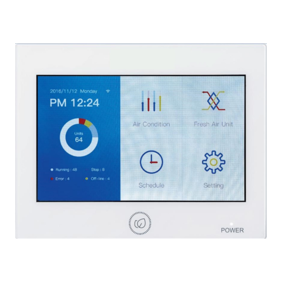
Function operation Initialization After powering on. controller starts to search for indoor units shown as picture 2 below: Picture 2 Home Page When search is completed, the home page will show as below, the left side shows the Qty. of indoor units connected and the Qty. of units in condition as On/Off/Error/Offline. PS: Picture ... - Page 11 Function operation Indoor units parameter and control To see the setting for each indoor unit, tap on Air Conditioning. Shown (Picture 4) are the icons indicate the On/Off, Mode, Set Temp, Ambient Temp, Fan Speed and Control Mode of the connected indoor units. Deep Blue is Auto Mode Light Blue is Cooling Mode Orange is Heating Mode...
- Page 12 Function operation Air condition name, AC-1_2 represents the gateway (ADV05) addressed as NO.1,and its central address is NO.2 Current mode is “cool” If there is a error at present, the icon is displayed. Current setting Current fan speed is “Auto” temperature Current control mode is Current room temprerature...
- Page 13 Function operation Tap the top right bottom pull list ,It shows the following interface: Picture 7 If tap “All-On Display Unit”, all the indoor units that are currently screened are fully opened, if tap “All-Off Display Unit”, all the currently screened indoor units close, if tap “Control All Display Unit”, the following interface is displayed:...
- Page 14 Function operation The quantity of indoor units controlled at present,by clicking the blue number can be used to select indoor units that need to be controlled. Return to the upper layer ON/OFF the unit/units Return to the Home Reduce the setting temperature Increase the setting temperature Picture 8 In the upper interface, you can control On/Off, mode, setting temperature, wind speed,...
- Page 15 Function operation Picture 9 You can check the indoor unit you need to select. The interface is as follows. Picture 10 After click “Confirm”, the following control interface is entered :...
- Page 16 Function operation Picture 11 Last in first out: the indoor unit will execute the last order send by central controller,wired controller or remote controller. For example, if firstly sending low fan speed order by central controller and then sending high fan speed orderby wired controller, the indoor unit will execute high fan speed. Central: central controller enjoys all functions while wired &remote controller can only control ON/ OFF of indoor units.
- Page 17 Function operation Picture 12 You can tap to select or cancel the indoor units that need to be displayed, in which blue is selected and white is not selected. Picture 13 After selecting, click “Confirm”, and as in Picture 13, the top left corner shows the number of indoor units displayed by the selected so that the user can choose the indoor unit state that needs to be displayed according to the needs.
- Page 18 Function operation Picture 14 Help Tap ”Help” to enter the “help” interface, slide left and right, or and tap the blue icon to show the basic functionality of the product, the lower right corner shows the product model and the program version number.
- Page 19 Function operation The controller can control up to 64 units. Picture 16 The central controller can monitor and control HRV, up to 4 units. Picture 17 The controller can On/Off the indoor units and check the fault code of the indoor units.
- Page 20 Function operation Picture 18 The central controller can add, delete and change the weekly timing control for individual units, groups of units and all units. At most 64 pieces shedules can be set. Picture 19 The user can set up and close the daylight saving time according to the needs. After the daylight saving time is opened, dates for start and end of DST can be set.
- Page 21 Function operation Picture 20 The controller can display the detailed information parameters of the indoor units. Picture 21 You can set the name of the indoor unit, you can view the fault code.
- Page 22 Function operation Schedule At most 64 schedules can be set. Tap on “Schedule”in the home interface. If schedule has been set, the set of schedule information is displayed. If you enter schedule for the first time, it will be blank like below. Picture 22 Tap the “+” at the lower right corner to add a new schedule. Next, select the indoor units. Blue represents the indoor units are selected.
- Page 23 Function operation After desired units or groups are selected, tap “Confirm” and enter interface as follows. You can set schedule on (start) and off (end) times, mode, temperature, control mode, Once, Cycle and Except. Tap “Edit”, to return to the indoor units selection interface. Picture 24 Tap “Confirm”, the display interface is as follows . Picture 25 Repeat steps to add another schedule.
- Page 24 Function operation Picture 26 To delete a schedule, firstly, tap the icon ‘-’ in the Picture 26,then small circle will appear like Picture 27,secondly, select the schedules to be deleted. Finally,press the icon ‘delete’ in the lower right corner Picture 27...
- Page 25 Function operation Picture 28 To make a schedule idle, tap on the “Unavailable” icon, see Picture 26. Tap the icon of the desired schedule(s) to idle. After tapping “Confirm”, it shows the schedule as “UNAVAILABLE” as seen in Picture 28. To reactivate a schedule that is idle then tap “Available” as seen at the bottom right of Picture 28.
- Page 26 Function operation Picture 30 You can set the exception time for the schedule, click “Edit” on the bottom of the week to add and modify the “Except Date”. Picture 31...
- Page 27 Function operation Picture 32 You can choose the date to add the “Except Date”. The “Except Date”represents the date when the corresponding schedule do not execute. The “Except Date”is set in the 6 months prior to the current date and within the time range of the current 2 years. Setting Tap “Setting”...
- Page 28 Function operation 1. General Picture 34 Slide up and down to the view all control settings. Picture 35 You can change the Backlight brightness, Screensaver time and Fahrenheit switch by taping and dragging the slider, and currently only support English.
- Page 29 Function operation 2. Time Picture 36 You can adjust the time by clicking the up and down arrow, you can taping 24HR and 12HR to switch 24 hours or 12 hours. Tap DST Picture 37 After taping ON, the interface is as follows. You can tap the button to adjust the start and of the daylight saving time, and the time of the daylight saving time.
- Page 30 Function operation Picture 38 3. Name Tap “Name” to enter the following interface. Picture 39 Tap the indoor unit to rename.
- Page 31 Function operation Picture 40 The upper left corner shows physical address: the” Physical address” of the machine, such as AC-5_4, represents the adapter address is 5, and the indoor centralized address is 4. It is convenient for the name and physical address to be checked It needs to be confirmed by “Done”...
- Page 32 Function operation Tap “+” Picture 42 Select indoor units to be added to a zone. Picture 43 Press” Confirm” to enter the following interface...
- Page 33 Function operation Picture 44 If you want to create a new group, press "+"button on lower right shown as picture 44 and select the indoor units to be added as picture 45 Picture 45 After press “Confirm”, add a new “Group”,as shown in Picture 46.
- Page 34 Function operation Picture 46 Tap "-" at the lower right ,then select the zone you want to delete,then tap "delete"to confirm. Picture 47...
- Page 35 Function operation Picture 48 Select a group then tap on current name to rename. Picture 49 Press “Done” to save.
- Page 36 Function operation Up to 16 energy saving parameters can be set. In Picture 33, tap “Eco”, Picture 50 Click “+” to add the indoor units that need to set energy saving. Picture 51...
- Page 37 Function operation After tap “Confirm”, enter the parameter settings of Eco, as shown in Picture 52. Picture 52 Slide up and down Picture 53 If you tap “Overrun” to ON, you can select Overrun's time, and it can be adjusted from 10- 240 minutes. Overrun mean the amount of time the temperatures can be set beyond the parameter by the user before the control returns it to within the limits set.
- Page 38 Function operation Picture 54 After tapping “Confirm”, the Eco setup information will show as seen in Picture 55. Picture 55 Tap “+” and repeat above steps to add another set of ECO parameters.
- Page 39 Function operation Picture 56 If an indoor unit is already included in a another ECO parameters, a warning prompt will appear. Picture 57 Tap “Confirm”...
- Page 40 Function operation Picture 58 If you press “Confirm”, it is set successfully, the conflict indoor unit is cancelled from the previous setting, and the final ECO confirmation is confirmed. If you press “Cancel”, it returns to the previous setting interface. After tap "-", select the indoor unit that needs to be deleted, tap “Delete”. Picture 59 If you tap “Cancel”,returns to the upper layer. Tap “Unavailable” to idle parameter settings. Press “Confirm” to save.
- Page 41 Function operation Picture 60 To restore idled parameters, tap “Available” then select the set that needs to be restored. Tap “Confirm” to save. Picture 61...
- Page 42 Function operation 5. Service Tap “Service” in Picture 33 and tap “Confirm” on pop up that prompts to enter password. Picture 62 Enter password 841226 and tap “Login”. Picture 63 After clicking “Login”, go into Picture 64.
- Page 43 Function operation Picture 64 (1) Mode Setting Click “Mode Setting” at the Picture 64 interface Picture 65 Select the system(s) that needs to be changed and tap the arrow to move to the next column.
- Page 44 Function operation Picture 66 select the corresponding gateway and tap "Cool Only " Picture 67 Tap “Confirm” to save changes.
- Page 45 Function operation Picture 68 (2) Error Tap “Error” in settings menu (Picture 64) to view errors. Picture 69 You can slide up and down to see the fault information of other indoor units. Up to 10 faults will be saved for each unit.
- Page 46 Function operation (3) Detail Tap “Detail” in the settings menu (Picture 64) to view unit details such as room temperature, mode, current running time and errors (if any). Picture 70 Other indoor units can be displayed by sliding up and down. (4) Tapping “Restore” and “Confirm” will reset the control to factory defaults and clear all settings.
- Page 47 Function operation If the system is connected with HRV, the main interface is displayed as follows Entering the “Help” interface,you can see the Current time type of the central controller,the version number of the program,and the simple introduction of the centralized control function. Click to enter the HRV indoor units The state of the HRV view and set interface.
- Page 48 Function operation Click on the control interface of the HRV units, Picture 74 Tap on the lower right-hand menu icon to turn all HRV units on or off. Picture 75 Tap on the next line of magnifying glass to select the HRV unit that you need to view...
- Page 49 Function operation Picture 76 Tap “LIST” to view the HRV in the list form. If the HRV is installed, the naming can be set at the Setting-Name interface Picture 77 If there is a HRV unit, then AC and HRV can be set separately in schedule, and AC and HRV can be set separately in the middle part of the bottom row.
- Page 50 Function operation Picture 78 If HRV existence, there is a ”Linkage“ interface on the ”Setting“ interface, which allows HRV to interact with ordinary indoor units, as follows Picture 79...
- Page 51 Function operation Tap “Linkage” to select which HRV unit to link then tap “Edit”. Picture 80 Select any of the indoor unit to link to the HRV unit. Blue indicates selected. Then tap “Confirm”. Picture 81 After the linkage, the selected linkage of the indoor units, all closed, the linkage of the HRV off, in the linkage process, the HRV machine can also be manual switch, the implementation of the priority principle, with the last operation as the criterion.
-
Page 52: Wiring Diagram And Installation
Wiring diagram and Installation RWV09 can connect with VRF system and HRV simultaneously. - Page 53 Wiring diagram and Installation Wiring diagram between central controller and converter gateway ADV05. ADV05 ADV05...
- Page 54 Wiring diagram and Installation All of the communication 485 cables between each module and terminal module to the central controller are double core shielded twisted-pair cable. Specific wiring as the table below: The length of signal line Wiring dimension ≤100 0.3 mm ×2 100<x≤200 0.5mm ×2 200<x≤300 0.75mm ×2 300<x≤400 1.25mm ×2 400<x≤500 ×2 Installation condition...
- Page 55 Wiring diagram and Installation Place the board, AB for 86 cassettes, CD for 120 cassettes. The hanger should be fixed as the picture, please note the UP direction. The hanging plate is placed in the direction of the illustration, where A/B is the location of the 86 cassette screws, and the C/D is the position of the 120 cassette screws. The pendant is fixed to the hole of the pendant, please pay attention to the UP direction.
- Page 56 Wiring diagram and Installation 485+ 485- 485+ 485- +V(red) -V(black) AC/N(blue) AC/L(brown)
- Page 57 Wiring diagram and Installation Wiring between power adapter and central controller. Central Controller Dimension:...
- Page 58 4. Third party interface Through the A1B1 interface, it can access third party devices, and can realize the monitoring and control of third party devices to the central controller. RWV09...
- Page 59 Wiring diagram and Installation Third party Modbus Communication parameter: Baud rate: 9600 data bits: 8 Check bit: None Stop bit: 1 One frame command finished,using CRC to check Single split and multi split Unit ID:1-16, SLAVE ID 33 Unit ID:1, SLAVE ID 29 Gateway’s address Unit ID:17-32, SLAVE ID 34 Unit ID:2, SLAVE ID 30 SLAVE ID (ranging from 1 to 32)
- Page 60 Wiring diagram and Installation 2. Coil--Query function code: 0x01 Control function code: 0x05/0x0F name meaning reamrk Read operation to get the current indoor unit on and off indoor unit 1 0- off status on off 1- on Write operation changes the indoor unit on and off state Read operation to get the current indoor unit on and off indoor unit 2 0-off...
- Page 61 Wiring diagram and Installation WORD name range remark This parameter is currently not indoor unit 2 HP 0.1HP supported and will return 0x7FFF …… Unit 1 °C, HRV1/HRV2/Fresh air indoor unit64 ‐ 30 ‐‐ 60 unit model without set temperature, ambient temp.
- Page 62 Wiring diagram and Installation 4. Hold Register (Holding Register) Query Function Code 0x03 Control Function Code 0x06/0x10 WORD name range remark Returns 0x7FFF if the corresponding indoor unit does not exist. Unit 1 °C indoor The air conditioner read operation acquires unit 1 set 16 - 30 the current operation mode, and the write...
- Page 63 Wiring diagram and Installation WORD name range remark air conditioning/HRV with coil: 1 ‐ low speed 2 ‐ mid speed Returns 0x7FFF if the corresponding 3 ‐ high speed indoor unit does not exist. indoor 4 ‐ auto speed Read operation to get the current fan unit 1 fan HRV1/HRV2/Fresh air unit : speed:...
- Page 64 Wiring diagram and Installation WORD name range remark air conditioning/HRV with coil: 1 ‐ cooling 2 ‐ heating Returns 0x7FFF if the corresponding 3 ‐ dehumidifying indoor unit does not exist. indoor 4 ‐ fan only The read operation gets the current run unit 64 5 ‐...
- Page 66 20-AW-RWV09 Central Controller-Installation manual-26112020-REV01-GB...
Need help?
Do you have a question about the RWV09 and is the answer not in the manual?
Questions and answers