
Related Manuals for Giga-Byte Communications MD60-SC0


Summary of Contents for Giga-Byte Communications MD60-SC0
- Page 1 MD60-SC0 MD60-SC1 Dual LGA2011 sockets R3 motherboard for Intel E5-2600 V3/V4 series processors ® User's Manual Rev. 1102...
- Page 2 Copyright © 2016 GIGA-BYTE TECHNOLOGY CO., LTD. All rights reserved. The trademarks mentioned in this manual are legally registered to their respective owners. Disclaimer Information in this manual is protected by copyright laws and is the property of GIGABYTE. Changes to the specifications and features in this manual may be made by GIGABYTE without prior notice.
-
Page 3: Table Of Contents
Table of Contents Box Contents ........................5 MD60-SC0 Motherboard Layout ..................6 Block Diagram .........................9 Chapter 1 Hardware Installation ...................10 Installation Precautions .................. 10 1-2 Product Specifications ..................11 Installing the CPU and CPU Cooler ............... 13 1-3-1 Installing the CPU ....................13 1-3-2 Installing the CPU Cooler ..................16... - Page 4 2-3-2-3 CPU T State Control ....................75 2-3-3 Common RefCode Configuration ................76 2-3-4 QPI Configuration ....................77 2-3-5 Memory Configuration ....................79 2-3-5-1 Memory Topology ....................81 2-3-5-2 Memory Thermal ....................82 2-3-5-3 Memory Map ......................83 2-3-5-4 Memory RAS Configuration ..................84 2-3-6 IIO Configuration ....................85 2-3-6-1 IOAT Configuration ....................86 2-3-6-2 Intel VT for Directed I/O (VT-d) ................87 2-3-7 PCH Configuration ....................88 2-3-7-1 PCH Devices ......................89 2-3-7-2 PCH sSATA Configuration ..................90...
-
Page 5: Box Contents
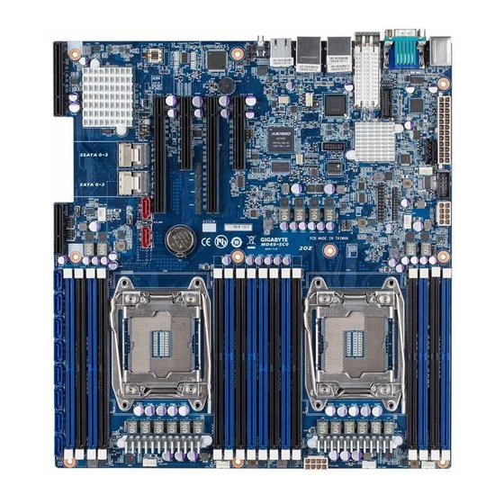
Box Contents Motherboard User's Manual Driver CD Two SAS 6Gb/s cables I/O Shield • The box contents above are for reference only and the actual items shall depend on the product package you obtain. The box contents are subject to change without notice. •... - Page 6 MD60-SC0/MD60-SC1 Motherboard Layout 6 7 8 63 64 65 66 67 59 60 - 6 -...
- Page 7 BMC Management LAN port USB3_LAN1 LAN1 port (top) / USB 3.0 ports (bottom) USB3_LAN2 LAN2 port (top) / USB 3.0 ports (bottom) QSFP_CAGE QSFP LAN port (MD60-SC0 Only) COM1_VGA Serial port (top)/VGA port (buttom) F_USB3 USB 3.0 header PS2_USB3 PS/2 connector (top)/USB 3.0 ports (buttom)
- Page 8 SAS 6Gb/s connectors (Gigabyte extension card SAS0~7 required) SAS_SGP2 SAS SGPIO header#2 RAID_SLOT2 PCI Express x4 slot (Proprietary slot) Battery socket SATA_DOM4 SATA port 4 DOM support jumper SATA5 SATA 3 6Gb/s connector SATA4 SATA 3 6Gb/s connector SATA_DOM5 SATA port 5 DOM support jumper CPU0_FAN CPU0 fan connector (for Primary CPU) CLR_CMOS...
-
Page 9: Block Diagram
Block Diagram - 9 -... -
Page 10: Chapter 1 Hardware Installation
Chapter 1 Hardware Installation Installation Precautions The motherboard contains numerous delicate electronic circuits and components which can become damaged as a result of electrostatic discharge (ESD). Prior to installation, carefully read the user's manual and follow these procedures: • Prior to installation, do not remove or break motherboard S/N (Serial Number) sticker or warranty sticker provided by your dealer. -
Page 11: Product Specifications
Š Intel I350 supports dual GbE LAN ports Š ® Intel 82599ES supports dual 10GbE LAN port (MD60-SC0 Only) Š ® 1 x Management LAN 10/100/1000Mpbs LAN port Š Option Intel XL710 supports 1 x 40GbE LAN port or 4 x 10GbE LAN ports Š... - Page 12 1 x IPMB connector Š Rear Panel I/O 6 x USB 3.0 ports Š 1 x QSPF LAN port (MD60-SC0 Only) Š 3 x RJ-45 ports (1 x 10/100/1000 Mbps dedicated management LAN port) Š 1 x COM port Š...
-
Page 13: Installing The Cpu And Cpu Cooler
Installing the CPU and CPU Cooler Read the following guidelines before you begin to install the CPU: • Make sure that the motherboard supports the CPU. • Always turn off the computer and unplug the power cord from the power outlet before installing the CPU to prevent hardware damage. - Page 14 B. Follow the steps below to correctly install the CPU into the motherboard CPU socket. • Before installing the CPU, make sure to turn off the computer and unplug the power cord from the power outlet to prevent damage to the CPU. •...
- Page 15 Lever B Lever A Step 5: Step 6: Once the CPU is properly inserted, carefully replace the Finally, secure lever A under its retention tab to load plate. Then secure lever B under its retention tab. complete the installation of the CPU. The protective plastic cover may pop off from the load plate during the process of engaging the lever.
-
Page 16: Installing The Cpu Cooler
1-3-2 Installing the CPU Cooler Refer to the steps below to correctly install the CPU cooler on the motherboard. (Actual installation process may differ depending the CPU cooler to be used. Refer to the user's manual for your CPU cooler.) Step 1: Step 2: Apply an even and thin layer of thermal grease on the... -
Page 17: Installing The Memory
Installing the Memory Read the following guidelines before you begin to install the memory: • Make sure that the motherboard supports the memory. It is recommended that memory of the same capacity, brand, speed, and chips be used. • Always turn off the computer and unplug the power cord from the power outlet before installing the memory to prevent hardware damage. -
Page 18: Installing A Memory
1-4-2 Installing a Memory Before installing a memory module, make sure to turn off the computer and unplug the power cord from the power outlet to prevent damage to the memory module. Be sure to install DDR4 DIMMs on this motherboard. Installation Step: Step 1. -
Page 19: Back Panel Connectors
The video in port allows connect to video in, which can also apply to video loop thru function. QSFP LAN Port (MD60-SC0 Only) The QSFP LAN port provides Internet connection at up to 40 Gbps data rate (based on the LAN chipset). - Page 20 Link Speed LED: Link/Activity LED: Speed LED Activity LED State Description State Description Yellow On 1 Gbps data rate Link bet ween system and net work or no Green On 100 Mbps data rate access 10 Mbps data rate Blinking Data transmission or receiving is occurring No data transmission or receiving is occurring 10/100/1000 LAN Port Speed LED...
-
Page 21: Internal Connectors
Internal Connectors ATX1 MINI_CN2 P12V_AUX2 SAS_SGP1 P12V_AUX1 SAS_SGP2 PMBUS F_USB3 CPU0_FAN (for primary CPU) FP_1 CPU1_FAN (for seconary CPU) BP_1 SYS_FAN1 (System Fan) COM2 SYS_FAN2 (System Fan) SYS_FAN3 (System Fan) LAN4_ACT SYS_FAN4 (System Fan) LAN3_ACT SYS_FAN5 (System Fan) MLAN_LINK SATA4 MLAN_ACT SATA5 IPMB... - Page 22 Read the following guidelines before connecting external devices: • First make sure your devices are compliant with the connectors you wish to connect. • Before installing the devices, be sure to turn off the devices and your computer. Unplug the power cord from the power outlet to prevent damage to the devices.
- Page 23 1/2/3) ATX1/P12V_AUX2/P12V_AUX1 (2x4 12V Power Connector and 2x12 Main Power Connector) With the use of the power connector, the power supply can supply enough stable power to all the components on the motherboard. Before connecting the power connector, first make sure the power supply is turned off and all devices are properly installed.
- Page 24 4) PMBUS (PMBus connector) Pin No. Definition PMBus CLK PMBus DATA PMBus Alert 3.3V Sense 5/6/7/8/9/10/11) CPU_FAN0/CPU_FAN1/SYS_FAN1/SYS_FAN2/SYS_FAN3/SYS_FAN4/ SYS_FAN5 (CPU Fan/System Fan Headers) The motherboard has two 4-pin CPU fan headers, and five 4-pin system fan headers. Most fan headers possess a foolproof insertion design. When connecting a fan cable, be sure to connect it in the correct orientation (the black connector wire is the ground wire).
- Page 25 12/13) SATA4/SATA5 (SATA 6Gb/s Connectors/Support SATA DOM Function) The SATA connectors conform to SATA 6Gb/s standard and are compatible with SATA 3Gb/s and 1.5Gb/s standard. Each SATA connector supports a single SATA device. Please see page 35 for SATA DOM jumper setting. Normal Mode: SATA DOM Mode: Pin No. Definition...
- Page 26 15/16) MINI_CN2/MINI_CN1 (Mini SAS cable connectors) The Mini SAS connectors conform to SATA 6Gb/s standard. Each Mini SAS connector supports four SATA device. MINI_CN2 MINI_CN1 Pin No. Definition Pin No. Definition RX0+ TX0+ RX0- TX0- RX1+ TX1+ RX1- TX1- SIB7 SIB0 SIB3 SIB1 SIB4 SIB2...
- Page 27 17/18) SAS_SGP1/SAS_SGP2 (SAS SGPIO Headers) SGPIO stands for Serial General Purpose Input/Output which is a 4-signal (or 4-wire) bus used between a Host Bus Adapter (HBA) and a backplane. Out of the 4 signals, 3 are driven by the HBA and 1 is driven by the backplane.
- Page 28 20) FP_1 (Front Panel Header) Connect the power switch, reset switch, chassis intrusion switch/sensor and system status indicator on the chassis to this header according to the pin assignments below. Note the positive and negative pins before connecting the cables. 23 24 Pin No. Signal Name Definition...
- Page 29 21) BP_1 (HDD Back Plane Board Hearders) Pin No. Definition BP_SGP_CLK BP_SGP_GLD FAN_GATE_N BP_SGP_DOUT Rreset BP_LED_A_N BP_LED_G_N 25 26 BP_SGP_DIN SMB_BP_DATA SMB_BP_CLK P_3V3_AUX BMC_ACK P_3V3_AUX BMC_REQ BP_PRESENSE - 29 - Hardware Installation...
- Page 30 22) COM2 (Serial Port Header) The COM header provides one serial port via an optional COM port cable. For purchasing the optional COM port cable, please contact the local dealer. Pin No. Definition NDCD- NSIN NSOUT NDTR- NDSR- NRTS- 9 10 NCTS- NRI- No Pin...
- Page 31 24/25) LAN4_ACT/LAN3_ACT(LAN4/LAN3 Active LED Header) LAN4_ACT LAN3_ACT Pin No. Definition LED+ LED- 26) MLAN_LINK (Management LAN Port Link LED Header) MLAN_LINK Pin No. Definition Link 1G Link 100 Mbps - 31 - Hardware Installation...
- Page 32 27) MLAN_ACT (Management LAN Port Active LED Header) MLAN_ACT Pin No. Definition Active 28) IPMB (IPMB Connector) Pin No. Definition Clock Data Hardware Installation - 32 -...
- Page 33 29) LED_BMC (BMC Firmware Readiness LED) State Description BMC firmware is initial Blinking BMC firmware is ready AC loss 30) BAT (Battery) The battery provides power to keep the values (such as BIOS configurations, date, and time information) in the CMOS when the computer is turned off. Replace the battery when the battery voltage drops to a low level, or the CMOS values may not be accurate or may be lost. •...
-
Page 34: Jumper Settings
Jumper Settings SATA_DOM4 BIOS_RCVR SATA_DOM5 ME_RCVR CLR_CMOS S3_MASK CASE_OPEN SW_RAID ME_UPDATE BMC_FRB BIOS_PWD Hardware Installation - 34 -... - Page 35 1/2) SATA_DOM4/SATA_DOM5 (SATA port 4 and port 5 DOM Jumpers) CAUTION! • If the SATA DOM power is supplied by the motherboard, set the jumper to pin 1-2. • If the SATA DOM power is supplied by external power, set the jumper to pin 2-3. • If a SATA type hard drive is connected to the motherboard, please ensure the jumper is closed and set to 2-3 pins (Default setting), in order to reduce any risk of hard disk damage.
- Page 36 4) CASE_OPEN (Chassis intrusion Header) Open: Normal operation (Default setting) CASE_OPEN Closed: Enable chassis intrusion alter. 5) ME_UPDATE (ME Update Jumper) 1-2 Close: Normal operation (Default setting) ME_UPDATE 2-3 Close: ME recovery mode. Hardware Installation - 36 -...
- Page 37 6) BIOS_PWD (Clearing Supervisor Password Jumper) BIOS_PWD 1-2 Close: Normal operation. (Default setting) 2-3 Close: Skip supervisor password. 7) BIOS_RCVR (BIOS Recovery Jumper) BIOS_RCVR 1-2 Close: Normal operation. (Default setting) 2-3 Close: BIOS recovery mode. - 37 - Hardware Installation...
- Page 38 8) ME_RCVR (ME Recovery Jumper) ME_RCVR 1-2 Close: Normal operation.(Default setting) 2-3 Close: ME recovery mode. 9) S3_MASK (S3 Power On Select Jumper) S3_MASK 1-2 Close: Stop an initial power on when BMC is not ready. 2-3 Close: Keep initial power on. (Default setting) Hardware Installation - 38 -...
- Page 39 10) SW_RAID (Intel/LSI Software RAID Key Header) SW_RAID 11) BMC_FRB (Force to Stop FRB Timer Jumper) 1-2 Close: Normal operation. (Default setting) 2-3 Close: Force to Stop FRB Timer. - 39 - Hardware Installation...
-
Page 40: Chapter 2 Bios Setup
Chapter 2 BIOS Setup BIOS (Basic Input and Output System) records hardware parameters of the system in the EFI on the motherboard. Its major functions include conducting the Power-On Self-Test (POST) during system startup, saving system parameters and loading operating system, etc. BIOS includes a BIOS Setup program that allows the user to modify basic system configuration settings or to activate certain system features. When the power is turned off, the battery on the motherboard supplies the necessary power to the CMOS to keep the configuration values in the CMOS. - Page 41 Main This setup page includes all the items in standard compatible BIOS. Advanced This setup page includes all the items of AMI BIOS special enhanced features. (ex: Auto detect fan and temperature status, automatically configure hard disk parameters.) Intel RC Setup This setup page includes all the submenu options for configuring the function of processor, network, North Bridge, South Bridge, and System event logs.
-
Page 42: The Main Menu
The Main Menu Once you enter the BIOS Setup program, the Main Menu (as shown below) appears on the screen. Use arrow keys to move among the items and press <Enter> to accept or enter other sub-menu. Main Menu Help The on-screen description of a highlighted setup option is displayed on the bottom line of the Main Menu. - Page 43 BIOS Information Porject Name Display the project name information. Porject Version Display version number of the BIOS setup utility. BIOS Build Date and Time Displays the date and time when the BIOS setup utility was created. BMC Information BMC Firmware Version Display BMC firmware version information.
- Page 44 Onboard LAN Information LAN1/LAN2/LAN3/LAN4 MAC Address Display LAN1/LAN2/LAN/LAN4 MAC address information. System Date Set the date following the weekday-month-day- year format. System Time Set the system time following the hour-minute- second format. BIOS Setup - 44 -...
-
Page 45: Advanced Menu
Advanced Menu The Advanced menu display submenu options for configuring the function of various hardware components. Select a submenu item, then press Enter to access the related submenu screen. - 45 - BIOS Setup... - Page 46 2-2-1 Serial Port Console Redirection BIOS Setup - 46 -...
- Page 47 - 47 - BIOS Setup...
- Page 48 COM1/COM2/Serial Over LAN Console Redirection Settings Console Redirection (Note) Select whether to enable console redirection for specified device. Console redirection enables users to manage the system from a remote location. Options available: Enabled/Disabled. Default setting is Disabled. Console Redirection Settings Terminal Type Select a terminal type to be used for console redirection. Options available: VT100/VT100+/ANSI /VT-UTF8. Default setting is ANSI. Bits per second Select the baud rate for console redirection.
- Page 49 Legacy OS Redirection Resolution (Note) On Legacy OS, the number of Rows and Columns supported redirection. Options available: 80x24/80X25. Default setting is 80x24. Putty KeyPad (Note) Select function FunctionKey and KeyPad on Putty. Options available: VT100/LINUX/XTERMR6/SCO/ESCN/VT400. Default setting is VT100. Redirection After BIOS POST (Note) This option allows user to enable console redirection after O.S has loaded.
-
Page 50: Pci Subsystem Settings
2-2-2 PCI Subsystem Settings PCI Express Slot #1/#2/#3/#4/#5 I/O ROM When enabled, This setting will initialize the device expansion ROM for the related PCI-E slot. Options available: Enabled/Disabled. Default setting is Enabled. Onboard LAN#1/#2/#3/#4 Controller Enable/Disable onboard LAN devices. Options available: Enabled/Disabled. Default setting is Enabled. Onboard LAN #1/#2/#3/#4 I/O ROM Enable/Disable onboard LAN devices and initialize device expansion ROM. -
Page 51: Pci Express Settings
SR-IOV Support If system has SR-IOV capable PCIe Devices, this option enables or disables Single Root IO Virtualization Support. Options available: Enabled/Disabled. Default setting is Disabled. PCI Express Settings Press [Enter] for configuration of advanced items. - 51 - BIOS Setup... - Page 52 2-2-2-1 PCI Express Settings PCI Express Device Register Settings Relaxed Ordering Enable/DIsable PCI Express Device Relaxed Ordering feature. Options available: Enabled/Disabled. Default setting is Disabled. Extended Tag Wnen this feature is enabled, the system will allow device to use 8-bit Tag field as a requester. Options available: Enabled/Disabled. Default setting is Disabled. No Snoop Enable/Disable PCI Express Device No Snoop option. Options available: Enabled/Disabled.
- Page 53 Link Training Timeout (us) Define the number of Microseconds software will wait before polling 'Link Training' bit in Link Status register. Press <+> / <-> keys to increase or decrease the desired values. Value rang is from 10 to 10000 us. Unpopulated Links When this item is set to 'Disable Link, the system will operate power save feature for those unpopulated PCI Express links.
-
Page 54: Network Stack
2-2-3 Network Stack Network stack Enable/Disable UEFI network stack. Options available: Enabled/DIsabled. Default setting is Disabled. Ipv4 PXE Support (Note) Enable/Disable Ipv4 PXE feature. Options available: Enabled/DIsabled. Default setting is Enabled. Ipv6 PXE Support (Note) Enable/Disable Ipv6 PXE feature. Options available: Enabled/DIsabled. Default setting is Enabled. PXE boot wait time (Note) Press <+>... -
Page 55: Csm Configuration
2-2-4 CSM Configuration Compatibility Support Module Configuration CSM Support Enable/Disable Compatibility Support Module (CSM) support. Options available: Enabled/Disabled. Default setting is Enabled. CSM16 Module Version Display CSM Module version information. Gate20 Active Upon Request: GA20 can be disabled using BIOS services. Always: Do not allow disabling GA20; this option is useful when any RT code is executed above 1MB. Options available: Upon Request/Always. - Page 56 Option ROM execution Network Controls the execution UEFI and Legacy PXE OpROM. Options available: Do not launch/UEFI/Legacy. Default setting is Legacy. Storage Controls the execution UEFI and Legacy Storage OpROM. Options available: Do not launch/UEFI/Legacy. Default setting is Legacy. Video Controls the execution UEFI and Legacy Video OpROM.
-
Page 57: Post Report Configuration
2-2-5 Post Report Configuration Post Report Configuration Error Message Report Post Error Message Enable/Disable Info Error Message support. Options available: Enabled/Disabled. Default setting is Enabled. - 57 - BIOS Setup... -
Page 58: Trusted Computing
2-2-6 Trusted Computing Configuration Security Device Support Select Enabled to activate TPM support feature. Options available: Enabled/Disabled. Default setting is Disabled. Current Status Information Display current TPM status information. BIOS Setup - 58 -... -
Page 59: Usb Configuration
2-2-7 USB Configuration USB Configuration USB Devices: Display the USB devices connected to the system. XHCI Hand-off Enable/Disable XHCI (USB 3.0) Hand-off support. Options available: Enabled/Disabled. Default setting is Enabled. EHCI Hand-off Enable/Disable EHCI (USB 2.0) Hand-off function. Options available: Enabled/Disabled. Default setting is Disabled. USB Mass Storage Driver Support (Note) Enable/Disable USB Mass Storage Driver Support. -
Page 60: Chipset Configuration
2-2-8 Chipset Configuration Restore on AC Power Loss (Note) Defines the power state to resume to after a system shutdown that is due to an interruption in AC power. When set to Last State, the system will return to the active power state prior to shutdown. When set to Stay Off, the system remains off after power shutdown. Options available: Last State/Stay Off/Power On. The default setting depends on the BMC setting. Deep Sleep (EuP) Enable/Disable Deep Sleep mode. -
Page 61: Sio Configuration
2-9 SIO Configuration - 61 - BIOS Setup... - Page 62 BIOS Setup - 62 -...
- Page 63 AMI SIO Driver Version Display the AMI SIO driver version information. Super IO Chip Logical Device(s) Configuration [*Active*] Serial Port 1/2 Press [Enter] for confuguration of advanced items. [*Active*] PS2 Keyboard Press [Enter] for confuguration of advanced items. [*Active*] PS2 Mouse Press [Enter] for confuguration of advanced items. Serial Port 1 Configuration Use This Device When enabled allows you to configure the serial port 1 settings. When set to Disabled, displays no...
- Page 64 IO=2E8h; IRQ=3,4,5,7,9,10,11,12; DMA; Default setting is Use Automatic Settings. Serial Port 2 Configuration Use This Device When enabled allows you to configure the serial port 2 settings. When set to Disabled, displays no configuration for the serial port. Options available: Enabled/Disabled. Default setting is Enabled. Logical Device Settings: Current: Display the Serial Port 2 base I/O addressand IRQ. Possible: Configure Serial Port 2 base I/O addressand IRQ. Option available: Use Automatic Settings/ IO=2F8h;...
-
Page 65: Iscsi Configuration
2-2-10 iSCSI Configuration iSCSI Initiator Name Add an Attempts Press [Enter] for configuration of advanced items. Delete Attempts Press [Enter] for configuration of advanced items. Change Attempt Order Press [Enter] for configuration of advanced items. - 65 - BIOS Setup... -
Page 66: Intel Rc Setup Menu
Intel RC Setup Menu Intel RC Setup menu displays submenu options for configuring the function of North Bridge and South Bridge. Select a submenu item, then press Enter to access the related submenu screen. RC Revision Display Intel RC version information. BIOS Setup - 66 -... - Page 67 2-3-1 Processor Configuration - 67 - BIOS Setup...
-
Page 68: Processor Configuration
Processor Configuration Pre-Socket Configuration Press [Enter] for configuration of advanced items. Processor Socket/Processor ID/Processor Frequency/Processor Max Raito/ Processor Min Raio/Microcode Revision/L1 Cache RAM/L2 Cache RAM/L3 Cache RAM/ Processor 0/1Version Displays the technical specifications for the installed processor. Hyper-Threading [All] The Hyper Threading Technology allows a single processor to execute two or more separate threads concurrently. When hyper-threading is enabled, multi-threaded software applications can execute their threads, thereby improving performance. - Page 69 Direct Cache Access (DCA) Options available: Auto/Enabled/Disabled. Default setting is Auto. DCA Prefetch Delay Options available: Disabled/8/16/24/32/40/48/56/64/72/80/88/96/104/112. Default setting is 32. X2APIC Options available: Enabled/Disabled. Default setting is Disabled. AES-NI Enable/Disable AES-NI (Intel Advanced Encryption Standard New Instructions) support function. Options available: Enabled/Disabled.
- Page 70 2-3-1-1 Pre-Socket Configuration BIOS Setup - 70 -...
- Page 71 CPU Socket 0/1 Configuration Press [Enter] for configuration of advanced items. Cores Enabled (for CPU socket 0/1) Number of Cores to enable. 0 means all cores. 14 Cores is available. Press the numeric keys to adjust desired values. - 71 - BIOS Setup...
-
Page 72: Advanced Power Management Configuration
2-3-2 Advanced Power Management Configuration Advanced Power Management Configuration Power Technology Option available:Disable/Energy Efficient/Custom. Default setting is Energy Efficient. Config TDP Options available: Enabled/Disabled. Default setting is Disabled. CPU P State Control Press [Enter] for configuration of advanced items. CPU C State Control Press [Enter] for configuration of advanced items. CPU T State Control Press [Enter] for configuration of advanced items. BIOS Setup - 72 -... -
Page 73: Cpu P State Control
2-3-2-1 CPU P State Control EIST (P-State) Conventional Intel SpeedStep Technology switches both voltage and frequency in tandem between high and low levels in response to processor load. Options available: Enabled/Disabled. Default setting is Enabled. Turbo Mode When this item is enabled, tje processor will automatically ramp up the clock speed of 1-2 of its processing cores to improve its performance. -
Page 74: Cpu C State Control
2-3-2-2 CPU C State Control Package C State Limit Configure state for the C-State package limit. Options available: C0/C1 state/C2 state/C6(non Retention) state/C6(Retention) state. Default setting is C6(non Retention) state. CPU C3/C6 Report Allows you to determine whether to let the CPU enter C3/C6 mode in system halt state. When enabled, the CPU core frequency and voltage will be reduced during system halt state to decrease power consumption. -
Page 75: Cpu T State Control
2-3-2-3 CPU T State Control ACPI T-States Enable/Disable CPU throttling by OS. Thorttling reduces power comsumption. Options available: Enabled/Disabled. Default setting is Enabled. - 75 - BIOS Setup... -
Page 76: Common Refcode Configuration
2-3-3 Common RefCode Configuration Common RefCode Configuration Isoc Mode Options available: Auto/Enabled/Disabled. Default setting is Auto. Numa (Non-Uniform Memory Access) Options available: Enabled/Disabled. Default setting is Enabled. BIOS Setup - 76 -... - Page 77 2-3-4 QPI Configuration - 77 - BIOS Setup...
-
Page 78: Qpi Configuration
QPI General Configuration Press [Enter] for configuration of advanced items. QPI Status Press [Enter] to view QPI status. Link Speed Mode Options available: Slow/Fast. Default setting is Fast. Link Frequency Select Options available: 6.4GB/s/8.0GB/s/9.6GB/s/Auto/Auto Limited. Default setting is Auto. BIOS Setup - 78 -... -
Page 79: Memory Configuration
2-3-5 Memory Configuration Integrated Memory Controller (iMC) Enforce POR Enable to enforce POR restrictions for DDR4 frequency and voltage programming. Options available: Enforce POR/Disabled/Enforce Stretch Goals. Default setting is Enforce POR. Memory Frequency Configure memory frequency. Options available: Auto/1333/1400/1600/1800/1867/2000/2133. Default setting is Auto. ECC Support Options available: Auto/Disabled/Enabled. -
Page 80: Memory Map
Memory Map Press [Enter] for configuration of advanced items. Memory RAS Configuration Press [Enter] for configuration of advanced items. BIOS Setup - 80 -... - Page 81 2-3-5-1 Memory Topology - 81 - BIOS Setup...
- Page 82 2-3-5-2 Memory Thermal Set Throttling Mode Configure Thermal Throttling Mode. Select OLTT or CLTT mode. Options available: Disabled/CLTT Mode. Default setting is CLTT Mode. MEMHOT Throttling Mode Options available: Disabled/Output-only/Input-only. Default setting is Input-only. BIOS Setup - 82 -...
- Page 83 2-3-5-3 Memory Map Socket Interleave Below 4GB Splits the 0-4GB address space between two sockets, so that both sockets get a chunk of local memory below 4GB. Options available: Disabled/Enabled. Default setting is Disabled. Channel Interleaving Options available: Auto/1-way Interleave/2-way Interleave/3-way Interleave/4-way Interleave. Default setting is Auto.
- Page 84 2-3-5-4 Memory RAS Configuration RAS Mode Enable/Disable RAS modes. Enabling Sparing and Mirroring is not supported. When this item is set to enabled, Sparing will be selected. Options available: Disable/Mirror/Lockstep Mode. Default setting is Disabled. Lockstep x4 DIMMs Options available: Auto/Disabled/Enabled. Default setting is Auto. Memory Rank Sparing Options available: Disabled/Enabled.
-
Page 85: Iio Configuration
2-3-6 IIO Configuration IIO Configuration EV DFX Features Set this option to allow DFX Lock Bits to remain clear. Options available: Enabled/Disabled. Default setting is Disabled. IOAT Configuration Press [Enter] for configuration of advanced items. Intel VT for Directed I/O (VT-d) Press [Enter] for configuration of advanced items. - 85 - BIOS Setup... - Page 86 2-3-6-1 IOAT Configuration IOAT Configuration Enable IOAT Control to enable/disable IOAT (Intel I/O Acceleration Technology) device. Options available: Enabled/Disabled. Default setting is Disabled. No Snoop Enable/Disable PCI Express Device No Snoop option. Options available: Enabled/Disabled. Default setting is Disabled. BIOS Setup - 86 -...
-
Page 87: Intel Vt For Directed I/O (Vt-D)
2-3-6-2 Intel VT for Directed I/O (VT-d) Intel VT for Directed I/O (VT-d) VT-d Azalea VCp Optimizations Enable/Disable Azalea VCp optimizations. Options available: Enabled/Disabled. Default setting is Disabled. Intel VT for Directed I/O (VT-d) Enable/Disable Intel VT for Directed I/O (VT-d) support function. Options available: Enabled/Disabled. -
Page 88: Pch Configuration
2-3-7 PCH Configuration PCH Configuration PCH Devices Press [Enter] for configuration of advanced items. PCH sSATA Configuration Press [Enter] for configuration of advanced items. PCH SATA Configuration Press [Enter] for configuration of advanced items. USB Configuration Press [Enter] for configuration of advanced items. BIOS Setup - 88 -... - Page 89 2-3-7-1 PCH Devices PCH CRID Enable/Disable Intel Compatible Revision ID. Options available: Enabled/Disabled. Default setting is Disabled. - 89 - BIOS Setup...
- Page 90 2-3-7-2 PCH sSATA Configuration BIOS Setup - 90 -...
-
Page 91: Sata Mode Options
When SATA Type is set to IDE PCH sSATA Configuration sSATA Controller(s) Enable/Disable sSATA controller. Options available: Enabled/Disabled. Default setting is Enabled. Configure sSATA as Coonfigure on chip SATA type. IDE Mode: When set to IDE, the SATA controller disables its RAID and AHCI functions and runs in the IDE emulation mode. - Page 92 Alternate Device ID on RAID Enable /Disable Alternate Device ID on RAID mode. Options available: Enabled/Disabled. Default setting is Disabled. Please note that this option appears when HDD is in RAID Mode. sSATA Port 0/1/2/3 The category identifies sSATA type of hard disk that are installed in the computer. System will automatically detect HDD type. Port 0/1/2/3 Enable/Disable Port 0/1/2/3 device.
-
Page 93: Sata Mode Options
2-3-7-2-1 SATA Mode Options When SATA Type is set to IDE/AHCI Mode SATA LED locate When this option is enabled, LED/SGPIO hardware is attached. Options available: Enabled/Disabled. Default setting is Enabled. - 93 - BIOS Setup... - Page 94 When SATA Type is set to RAID Mode SATA LED locate When this option is enabled, LED/SGPIO hardware is attached. Options available: Enabled/Disabled. Default setting is Enabled. Intel Rapid Recovery Technology Enable/Disable Intel Rapid Recovery Technology support function. Options available: Enabled/Disabled. Default setting is Enabled. RAID Option ROM UI banner Options available: Enabled/Disabled.
- Page 95 2-3-7-3 PCH SATA Configuration - 95 - BIOS Setup...
- Page 96 When SATA Type is set to IDE PCH SATA Configuration SATA Controller(s) Enable/Disable sSATA controller. Options available: Enabled/Disabled. Default setting is Enabled. Configure sSATA as Coonfigure on chip SATA type. IDE Mode: When set to IDE, the SATA controller disables its RAID and AHCI functions and runs in the IDE emulation mode.
- Page 97 Support Aggressive Link Power Mana (Note) Enable PCH to aggressively enter link power state. Options available: Enabled/Disabled. Default setting is Enabled. Alternate Device ID on RAID Enable /Disable Alternate Device ID on RAID mode. Options available: Enabled/Disabled. Default setting is Disabled. Please note that this option appears when HDD is in RAID Mode.
- Page 98 2-3-7-3-1 SATA Mode Options When SATA Type is set to IDE/AHCI Mode SATA LED locate When this option is enabled, LED/SGPIO hardware is attached. Options available: Enabled/Disabled. Default setting is Enabled. BIOS Setup - 98 -...
- Page 99 When SATA Type is set to RAID Mode SATA LED locate When this option is enabled, LED/SGPIO hardware is attached. Options available: Enabled/Disabled. Default setting is Enabled. Intel Rapid Recovery Technology Enable/Disable Intel Rapid Recovery Technology support function. Options available: Enabled/Disabled. Default setting is Enabled. RAID Option ROM UI banner Options available: Enabled/Disabled.
-
Page 100: Usb Configuration
2-3-7-4 USB Configuration USB Precondition Precondition work on USB host conteoller and root ports for faster enumeration. Options available: Enabled/Disabled. Default setting is Disabled. xHCI Mode Enable/Disable xHCI (USB 3.0) support function. Options available: Smart Auto/Enabled/Disabled. Default setting is Smart Auto. BIOS Setup - 100 -... -
Page 101: Miscellaneous Configuration
2-3-8 Miscellaneous Configuration Miscellaneous Configuration Active Video Select active Video type. Options available: Onboard Device/Offboard Device. Default setting is Offboard Device. - 101 - BIOS Setup... -
Page 102: Server Me Configuration
2-3-9 Server ME Configuration Greneral ME Configuration Operational Firmware Version Display Operational Firmware Version information. Recovery Firmware Version Display Recovery Firmware Version information. ME Firmware Features Display ME Firmware features information. ME Firmware Status #1/#2 Display ME Firmware status information. Current State (for ME Firmware) Display ME Firmware current status information. -
Page 103: Runtime Error Logging
2-3-10 Runtime Error Logging Runtime Error Logging System Errors Enable/Disable system error logging function. Options available: Enabled/Disabled. Default setting is Enabled. S/W Error Injection Support Enable/Disable software injection error logging function. Options available: Enabled/Disabled. Default setting is Disabled. Whea Settings Press [Enter] for configuration of advanced items. -
Page 104: Whea Setting
2-3-10-1 Whea Setting WHEA Support (Windows Hardware Error Architecture) Enable/Disable WHEA Support. Options available: Enabled/Disabled. Default setting is Enabled. BIOS Setup - 104 -... -
Page 105: Memory Error Enabling
2-3-10-2 Memory Error Enabling Memory Error Enabling Un-Correctable Errors disable Memory Options available: Enabled/Disabled. Default setting is Disabled. Memory corrected Errors enabling Options available: Enabled/Disabled. Default setting is Disabled. - 105 - BIOS Setup... -
Page 106: Pci/Pci Error Enabling
2-3-10-3 PCI/PCI Error Enabling PCI-Ex Error Enable (Note) Options available: Yes/No. Default setting is No. Corrected Error Enable Options available: Enabled/Disabled. Default setting is Disabled. Uncorrected Error Enable Options available: Enabled/Disabled. Default setting is Enabled. Fatal Error Enable Options available: Enabled/Disabled. Default setting is Enabled. Enable SERR propagation When this item is set to enabled, PCI bus system error (SERR) is generated and is routed to NMI. -
Page 107: Server Management Menu
Server Management Menu FRB-2 Timer Enable/Disable FRB-2 timer (POST timer). Options available: Enabled/Disabled. Default setting is Disabled. FRB2 Timer timeout Configure the FRB2 Timer timeout. Options available: 3 minutes/4 minutes/5 minutes/6 minutes. Default setting is 6 minutes. Please note that this item is configurable when FRB-2 Timer is set to Enabled. FRB2 Timer Policy Configure the FRB2 Timer policy. Options available: Do Nothing/Reset/Power Down. Default setting is Do Nothing. Please note that this item is configurable when FRB-2 Timer is set to Enabled. -
Page 108: System Event Log
System Event Log Press [Enter] for configuration of advanced items. View FRU Information Press [Enter] to view the advanced items. BMC network configuration Press [Enter] for configuration of advanced items. BIOS Setup - 108 -... - Page 109 2-4-1 System Event Log Enabling/Disabling Options SEL Components Change this to enable or disable all features of System Event Logging during boot. Options available: Enabled/Disabled. Default setting is Enabled. Erasing Settings Erasing SEL Choose options for erasing SEL. Options available: No/Yes, On next reset/Yes, On every reset. Default setting is No. When SEL is Full Choose options for reactions to a full SEL.
- Page 110 2-4-2 View FRU Information The FRU page is a simple display page for basic system ID information, as well as System product information. Items on this window are non-configurable. BIOS Setup - 110 -...
- Page 111 2-4-3 BMC network configuration BMC network configuration Select NCSI and Dedicated LAN Switch NCSI and dedicated LAN and send KCS command. Options available: Mode2(NSCI)/ Mode1 (Dedicated)/Do Nothing. Default setting is Do Nothing. Lan Channel 1 Configuration Address source Select to configure LAN channel parameters statically or dynamically (DHCP). Do nothing option willnot modify any BMC network parameters during BIOS phase. Options available: Unspecified/Static/DynamicBmcDhcp. Default setting is Unspecified/Static.
-
Page 112: Security Menu
Security Menu The Security menu allows you to safeguard and protect the system from unauthorized use by setting up access passwords. Administrator Password Press Enter to configure the Administrator password. User Password Press Enter to configure the user password. Secure Boot menu Press [Enter] for configuration of advanced items. BIOS Setup - 112 -... -
Page 113: Secure Boot Menu
2-5-1 Secure Boot menu The Secure Boot Menu is applicable when your device is installed the Windows 8 operatin system. ® Secure Mode Display the System secure mode state. Secure Boot Display the status of Secure Boot. Secure Boot Enable/Disable Secure Boot function. Options available: Enabled/Disabled. -
Page 114: Key Management
2-5-1-1 Key Management Default Key Provisioning Force the system to Setup Mode. This will clear all Secure Boot Variables such as Platform Key (PK), Key-exchange Key (KEK), Authorized Signature Database (db), and Forbidden Signaures Database (dbx). Options available: Enabled/Disabled. Default setting is Disabled. Enroll All Factory Default Keys Press [Enter] to install all factory default keys. - Page 115 Append Var to KEK Press [Enter] to load additional KEK from a storage devices for an additional db and dbx management. Authorized Signature Database (DB) Display the status of Authorized Signature Database. Delete DB Press [Enter] to delete the db from your system. Set new DB Press [Enter] to configure a new db.
-
Page 116: Boot Menu
Boot Menu The Boot menu allows you to set the drive priority during system boot-up. BIOS setup will display an error message if the legacy drive(s) specified is not bootable. Boot Configuration Setup Prompt Timeout Number of seconds to wait for setup activation key. 65535(0xFFFF) means indefinite waiting." Press the numberic keys to input the desired value. Bootup NumLock State Enable or Disable Bootup NumLock function. Options available: On/Off. - Page 117 Network Device BBS Priorities Press Enter to configure the boot priority. Hard Drive BBS Priorities Press Enter to configure the boot priority. - 117 - BIOS Setup...
-
Page 118: Save & Exit Menu
Save & Exit Menu The Exit menu displays the various options to quit from the BIOS setup. Highlight any of the exit options then press Enter. Save Changes and Exit Saves changes made and close the BIOS setup. Options available: Yes/No. Discard Changes and Exit Discards changes made and exit the BIOS setup. - Page 119 Boot Override Press Enter to configure the device as the boot-up drive. UEFI: Built-in in EFI Shell Press <Enter> on this item to Launch EFI Shell from filesystem device. - 119 - BIOS Setup...
-
Page 120: Bios Post Codes
BIOS POST Codes PEI_CORE_STARTED 0x10 PEI_CAR_CPU_INIT 0x11 // reserved for CPU 0x12 - 0x14 PEI_CAR_NB_INIT 0x15 // reserved for NB 0x16 - 0x18 PEI_CAR_SB_INIT 0x19 // reserved for SB 0x1A - 0x1C PEI_MEMORY_SPD_READ 0x1D PEI_MEMORY_PRESENCE_DETECT 0x1E PEI_MEMORY_TIMING 0x1F PEI_MEMORY_CONFIGURING 0x20 PEI_MEMORY_INIT 0x21 // reserved for OEM use: 0x22 - 0x2F... - Page 121 DXE_SBRUN_INIT 0x62 DXE_CPU_INIT 0x63 //reserved for CPU 0x64 - 0x67 DXE_NB_HB_INIT 0x68 DXE_NB_INIT 0x69 DXE_NB_SMM_INIT 0x6A //reserved for NB 0x6B - 0x6F DXE_SB_INIT 0x70 DXE_SB_SMM_INIT 0x71 DXE_SB_DEVICES_INIT 0x72 //reserved for SB 0x73 - 0x77 DXE_ACPI_INIT 0x78 DXE_CSM_INIT 0x79 //reserved for AMI use: 0x7A - 0x7F //reserved for OEM use: 0x80 - 0x8F DXE_BDS_STARTED 0x90...
- Page 122 DXE_SETUP_INPUT_WAIT 0xAC DXE_READY_TO_BOOT 0xAD DXE_LEGACY_BOOT 0xAE DXE_EXIT_BOOT_SERVICES 0xAF RT_SET_VIRTUAL_ADDRESS_MAP_BEGIN 0xB0 RT_SET_VIRTUAL_ADDRESS_MAP_END 0xB1 DXE_LEGACY_OPROM_INIT 0xB2 DXE_RESET_SYSTEM 0xB3 DXE_USB_HOTPLUG 0xB4 DXE_PCI_BUS_HOTPLUG 0xB5 DXE_NVRAM_CLEANUP 0xB6 DXE_CONFIGURATION_RESET 0xB7 //reserved for AMI use: 0xB8 - 0xBF //reserved for OEM use: 0xC0 - 0xCF //PEI_STATUS_CODE //Errors //Regular boot PEI_MEMORY_INVALID_TYPE 0x50...
- Page 123 //S3 Resume PEI_MEMORY_S3_RESUME_FAILED 0xE8 PEI_S3_RESUME_PPI_NOT_FOUND 0xE9 PEI_S3_BOOT_SCRIPT_ERROR 0xEA PEI_S3_OS_WAKE_ERROR 0xEB //reserved for AMI use: 0xEC - 0xEF // DXE_STATUS_CODE DXE_CPU_ERROR 0xD0 DXE_NB_ERROR 0xD1 DXE_SB_ERROR 0xD2 DXE_ARCH_PROTOCOL_NOT_AVAILABLE 0xD3 DXE_PCI_BUS_OUT_OF_RESOURCES 0xD4 DXE_LEGACY_OPROM_NO_SPACE 0xD5 DXE_NO_CON_OUT 0xD6 DXE_NO_CON_IN 0xD7 DXE_INVALID_PASSWORD 0xD8 DXE_BOOT_OPTION_LOAD_ERROR 0xD9 DXE_BOOT_OPTION_FAILED 0xDA DXE_FLASH_UPDATE_FAILED 0xDB...
-
Page 124: Bios Post Beep Code
BIOS POST Beep code 2-9-1 PEI Beep Codes # of Beeps Description Memory not Installed. Memory was installed twice (InstallPeiMemory routine in PEI Core called twice) Recovery started DXEIPL was not found DXE Core Firmware Volume was not found Recovery failed S3 Resume failed Reset PPI is not available 2-9-2 DEX Beep Codes... -
Page 125: Bios Recovery Instruction
2-10 BIOS Recovery Instruction The system has an embedded recovery technique. In the event that the BIOS becomes corrupt the boot block can be used to restore the BIOS to a working state. To restore your BIOS, please follow the instructions listed below: Recovery Instruction: Change xxx.ROM to amiboot.rom. -
Page 126: Chapter 3 Appendix
Chapter 3 Appendix Regulatory Statements Regulatory Notices This document must not be copied without our written permission, and the contents there of must not be imparted to a third party nor be used for any unauthorized purpose. Contravention will be prosecuted. We believe that the information contained herein was accurate in all respects at the time of printing. - Page 127 Finally, we suggest that you practice other environmentally friendly actions by understanding and using the energy-saving features of this product (where applicable), recycling the inner and outer packaging (including shipping containers) this product was delivered in, and by disposing of or recycling used batteries properly. With your help, we can reduce the amount of natural resources needed to produce electrical and electronic equipment, minimize the use of landfills for the disposal of "end of life" products, and generally improve our quality of life by ensuring that potentially hazardous substances are not released into the environment and...
Need help?
Do you have a question about the MD60-SC0 and is the answer not in the manual?
Questions and answers