Table of Contents
Advertisement
Quick Links
ML10 SERIES
ML10 SERIES
MECHANICAL VEHICLE RESTRAINT SYSTEM
INSTALLATION & OWNER'S MANUAL
DO NOT INSTALL, OPERATE OR SERVICE THIS PRODUCT UNLESS YOU HAVE READ AND
FULLY UNDERSTOOD THE ENTIRE CONTENTS OF THIS MANUAL. FAILURE TO DO SO MAY
RESULT IN PROPERTY DAMAGE, BODILY INJURY OR DEATH.
Mechanical Vehicle Restraint System Issue Date: October 26, 2009. (Part# 038-538E) Rev.2
Advertisement
Table of Contents

Summary of Contents for Blue Giant ML10 Series
- Page 1 ML10 SERIES ML10 SERIES MECHANICAL VEHICLE RESTRAINT SYSTEM INSTALLATION & OWNER’S MANUAL DO NOT INSTALL, OPERATE OR SERVICE THIS PRODUCT UNLESS YOU HAVE READ AND FULLY UNDERSTOOD THE ENTIRE CONTENTS OF THIS MANUAL. FAILURE TO DO SO MAY RESULT IN PROPERTY DAMAGE, BODILY INJURY OR DEATH.
-
Page 2: Table Of Contents
TABLE OF CONTENTS ABOUT THE ML10 MECHANICAL VEHICLE RESTRAINT 1.1 Owner’s Purchase Record INTRODUCTION 2.1 Exclusion of Liability 2.2 Manufacturer's Note OPERATOR’S MANUAL SAFETY MESSAGE COLOR IDENTIFICATION 3.1 Identifying Safety Warning Labels And Serial Plate Specifications INSTALLATION INSTRUCTIONS 4.1 Installation Inspection OPERATING INSTRUCTIONS 5.1 Engage Restraint 5.2 Disengage Restraint... -
Page 3: About The Ml10 Mechanical Vehicle Restraint
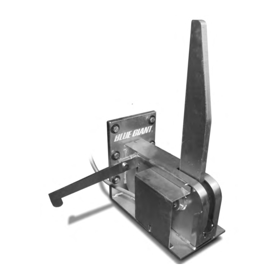
MECHANICAL VEHICLE RESTRAINT SYSTEM ABOUT THE ML10 MECHANICAL VEHICLE RESTRAINT The Blue Giant ML10 Mechanical Vehicle Restraint is a high performance yet low cost solution for loading docks worldwide. Its many features and benefits include: • A restraining power of 30,000 lbs (13,636 kg). -
Page 4: Introduction
WARRANTY INFORMATION Thank you for purchasing Blue Giant products. We appreciate your business, and are confident that our product will serve you for many years to come. In the event that you experience a problem with our product, our Warranty Center is here to support the Blue Giant Product(s) that you have purchased. -
Page 5: Operator's Manual Safety Message Color Identification
MECHANICAL VEHICLE RESTRAINT SYSTEM OPERATOR’S MANUAL SAFETY MESSAGE COLOR IDENTIFICATION This manual includes color-coded safety messages that clarify instructions and specify areas where potential hazard exists. To prevent the possibility of equipment damage and serious injury or death, please observe strictly the instructions and warnings contained in the messages. -
Page 6: Installation Instructions
MECHANICAL VEHICLE RESTRAINT SYSTEM INSTALLATION INSTRUCTIONS Installation must only be performed by trained and authorized personnel. Prior to installation, place adequate barriers to prevent vehicle traffic from entering the work area. Use caution when unbanding the Vehicle Restraint. Keep hands and feet clear of pinch points and wear appropriate safety attire. -
Page 7: Operating Instructions
MECHANICAL VEHICLE RESTRAINT SYSTEM OPERATING INSTRUCTIONS Engage Restraint When the freight carrier reverses into position firmly against the dock bumpers, activate the ML10 by using the Control Rod to press down on the Engagement Arm until the Restraint Arm is in the fully vertical position. Vehicle is not restrained if the Restraining Arm is not fully vertical. -
Page 8: Maintenance
PLANNED MAINTENANCE Planned Maintenance In addition to the daily operator inspection, Blue Giant recommends (and government regulations may require) that a planned maintenance and safety inspection program (PM) be performed by a trained and authorized mechanic on a regular basis to keep your equipment in safe operating condition. The PM will provide an opportunity to make a thorough inspection of the Vehicle Restraint’s operating condition. -
Page 9: Operator's Daily Checklist
MECHANICAL VEHICLE RESTRAINT SYSTEM MAINTENANCE Operator’s Daily Checklist INSTRUCTIONS FOR USE: Indicate “OK for Use” with a check mark ( ) in the appropriate box of each inspection point. Visually inspect the Vehicle Restraint and take note of obvious damage that may have been caused by operation during the last shift. -
Page 10: Troubleshooting
MECHANICAL VEHICLE RESTRAINT SYSTEM TROUBLESHOOTING Do not attempt to install, make repairs or adjustments. Only a trained and authorized service technician should perform the installation process. Contact your local dealer or distributor for assistance. PROBLEM PROBLEM CAUSE Restraining Arm will not 1. -
Page 11: Mechanical Components- Standard
MECHANICAL VEHICLE RESTRAINT SYSTEM MECHANICAL COMPONENTS- STANDARD ITEM PART NO. DESCRIPTION 522-5003C BODY WELDMENT 522-5004C LOCKING ARM ASSEMBLY 522-5005A SHAFT ARM ASSEMBLY 011-141 ¼-20 UNC. X 3.5 LG. HEX HEAD CAPSCREW 011-506 ¼-20 UNC HEX NUT 091-041 BUMPER 019-500 ¼” STRAIGHT GREASE NIPPLE 013-066 5/32”... -
Page 12: Mechanical Components- Optional
MECHANICAL VEHICLE RESTRAINT SYSTEM MECHANICAL COMPONENTS- OPTIONAL PROTECTIVE COVER REMOVED FOR CLARITY ITEM PART NO. DESCRIPTION 028-200 Proximity Sensor 52-003236 Proximity Holder 52-003245 Wand Cam 119-722 Protective Cover (not shown) - Page 13 MECHANICAL VEHICLE RESTRAINT SYSTEM NOTES...
- Page 14 MECHANICAL VEHICLE RESTRAINT SYSTEM NOTES...
- Page 15 MECHANICAL VEHICLE RESTRAINT SYSTEM NOTES...
- Page 16 B L U E G I A N T E Q U I P M E N T C O R P O R A T I O N © 2012 Blue Giant Equipment Corporation if calling within North America:...
Need help?
Do you have a question about the ML10 Series and is the answer not in the manual?
Questions and answers