Table of Contents
Advertisement
Quick Links
Advertisement
Table of Contents

Summary of Contents for Elabs DVPS44
- Page 1 DVPS44 Video Wall Processor & Matrix Switch 4x4 HDMI™ Scaler ...
- Page 2 THIS PAGE IS LEFT INTENTIONALLY BLANK...
- Page 3 HDMI™ Scaler has been tested for conformance to safety regula- tions and requirements, and has been certified for international use. However, like all electronic equipments, the DVPS44 should be used with care. Please read and follow the safety instructions to protect yourself from possible injury and to minimize the risk of damage to the unit.
-
Page 4: Table Of Contents
TABLE OF CONTENTS INTRODUCTION..............3 FEATURES................4 SPECIFICATIONS..............5 PACKAGE CONTENTS............6 HARDWARE INSTALLATION............ 7 CONNECTION DIAGRAM.............8 PANEL DESCRIPTIONS............10 OPERATION BY FRONT PANEL..........11 OPERATION BY REMOTE CONTROL ......... 13 OPERATION BY SOFTWARE CONTROL ......... 15 EDID LEARNING........…………………..18 EDID LEARNING FUNCTION............22 WARRANTY................23... -
Page 5: Introduction
The DVPS44 Video Wall Processor and Matrix Switch 4x4 HDMI Scal- er provides the most flexible and cost effective solution in the market. The new DVPS44 can be used as a conventional matrix switch, routing up to four different HDMI video sources to any monitor independently or be used as video wall processor, splitting a chosen image from one source to four displays. -
Page 6: Features
Features • HDCP compliant • Allows any HDMI display to view any HDMI source at any time • Supports default HDMI EDID and learns the EDID of displays • Supports HDMI™ DVI input, from 640x480 to 1920x1200@60, interlaced or progressive •... -
Page 7: Specifications
Specifications Technical Typical usage True 4x4 Matrix, Wall Processor HDCP compliance Video bandwidth Single-link 225MHz [6.75Gbps] Video support 480i/480p/720p/1080i/1080p60/1920x1200@60Hs 30-bit color HDMI/DVI Video Format Support Video loop-out Audio support Up to 7.1ch Surround Sound of Stereo Digital Audio Human body model — ± 19kV [air-gap discharge] ESD protection &... -
Page 8: Package Contents
Package Contents • 1x DVPS44 • 1x IR Remote Control • 1x Power Adapter DC 12V 5A • 1x Rack-mounting ear set • 1x User Manual • 1x Installation software CD... -
Page 9: Connection Diagram
INSTALLATION 1. Connect all HDMI sources to the HDMI Inputs of the DVPS44 Video Wall Processor and Matrix Switch 4x4 HDMI Scaler 2. Connect all displays (Monitors) to the HDMI Outputs of the DVPS44 3. Connect the RS232 controller cable from the DVPS44 to a PC 4. - Page 10 Example Connection Diagram Cont. Used as Matrix Switch: You can control the unit by Front panel or IR remote control or RS232. Any of the 4 inputs may be routed to any output. Used as Matrix Switch: You can control the unit by Front panel or IR remote control or RS232. Unit has 4 inputs, displays are showing 2 or 3 of the same input.
- Page 11 Example Connection Diagram Cont. Unit has 4 inputs, all displays are showing same input.
-
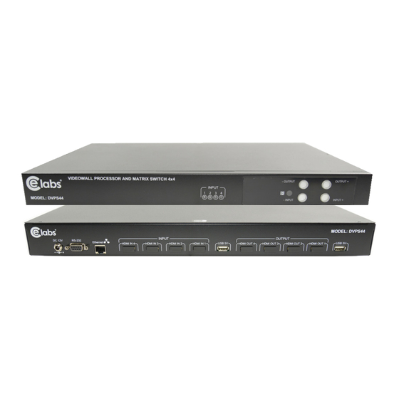
Page 12: Panel Descriptions
PANEL DESCRIPTION Front Panel 1. Input Status: indicate which Input is connected or activated 2. IR SENSOR: IR receiver commands. 3. Top 7-segment display: show the output display selected to be setup. “– Output“ push button: to Select in descending order, the output Display that will be setup. - Page 13 OPERATION Front Panel Push-Buttons preset save learn default 1. FRONT PANEL INPUT & OUTPUT SELECTION 1– Use the “– OUTPUT“ push button: to Select in descending order the output Display that will be setup. You will be see the selection on the top 7-segment display.
-
Page 14: Edid Learning
OPERATION CONT. 3. PRESET MAPPING MODE 1– Push “– OUTPUT“ (preset) button until the output LED shows “P.” to enter the Preset Mode. 2– Use the “INPUT+“ or “– INPUT“ push button to select the preview saved mapping configuration (from 0~7) to which you want to recall. 3–... - Page 15 OPERATION CONT. IR Remote Control Input/Output Select Push the button on the X (input) Y (output) keyboard to select Input & Output port. Example: Select Input 3 to Output 4. Push the red button as shown to select Input 3 to Output 4. Function Key Definition BUTTON FUNCTION ...
- Page 16 PROCEDURE 7-SEGMENT DISPLAY Status + A thru D Output Status: (Output 1 thru 4) + Take – 1. Press “STATUS” button – Ex: What Selections 2. Press “B” to select Output 2 are on Output 2 – (If Input 3 is selected) 3.
- Page 17 Software Control through RS-232 port System Requirement 1– OS Information: MS WinXP/7 2– Baud rates: 9600 3– Software size: 3 MB 4– Minimum RAM requirement: 256 MB Software Bottom Description 1 Display Firmware and software Version 9 EDID Setting 2 Connect/Disconnect RS-232 10 Firmware Update 3 Connect/Disconnect Ethernet...
- Page 18 1. Display Firmware and Software Version • Click Display Firmware and Software Version button to show version information 2. Connect/Disconnect RS-232 Button 1– Click Connect/Disconnect RS-232 button to connect to the RS-232 control port. 2– If RS-232 is connected, the button will show the sign image. 3.
- Page 19 8. Advanced Setting • Select the Advanced Setting button • Select Read Setting From Device then data will show in left portion of each window output 1-4 (information) • Go to STEP 1 portion and verify the values. If needed, enter new values on the Horizontal Start/End and Vertical Start/End then ...
- Page 20 9. EDID Button 1. Learn EDID from Default • Select one of the eight preset Default EDID at “From“ • Select the Input (1 thru 4) at “To“ • Select “Learn” button to learn default EDID for that specific input 2.
- Page 21 4. Create EDID File • Select “Create” button to create EDID file • Select the “EDID content” • Select the “HDTV”, “VESA”, “Audio”, “3D support”, and add the “Monitor Name” • Select “Save EDID on Computer” to save the generated EDID 5.
- Page 22 10. Firmware Update Button Make sure the RS-232 cable is connect to the computer and the DVPS44 unit, the RS232 button is selected on the software and the connecting status is connected • Select FIRMWARE UPDATE • Select Load File to select the firmware file which you want to update •...
- Page 23 13. Default Reset Button Select this button to do factory default reset. All settings previously made will be lost. The default reset process will take about 80~90 seconds. 14. In/Out Switch Button • Click the button on the checkerboard to select Input & Output port ...
-
Page 24: Edid Learning Function
HDMI signal output would most likely be the safest choice. The user can force the DVPS44 to learn the EDID of the lowest capable HDMI display among the others to make sure all displays are capable to display the HDMI signals normally. -
Page 25: Warranty
WARRANTY CE labs warrants the DVPS44 Video Wall Processor and Matrix Switch 4x4 HDMI Scaler, free from defects in the material and workmanship for 1 year from the date of purchase from the CE labs or an authorized dealer. Should this product fail to be in good working order within “One”... - Page 26 INSTALLER NOTES Purchasing Date: S/N:...
- Page 27 INSTALLER NOTES Purchasing Date: S/N:...
- Page 28 CE labs can support many areas of your audio and video distribution needs. We manufacture: • Digital Signage software and Media Players • HD Matrix Switchers • RF amplifiers • HDMI and Component HD distribution amplifiers • CAT 5 Signal Extender s •...
Need help?
Do you have a question about the DVPS44 and is the answer not in the manual?
Questions and answers