Table of Contents
Advertisement
Quick Links
Connective Peripherals
USB to Serial Converters Manual
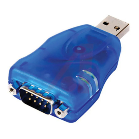
The ES-U-xxxx-x adapters are a series of USB Serial Converters from Connective Peripherals Pte Ltd.
They provide a simple method of adapting legacy RS-232 or RS-422/485 devices to work with modern
USB ports using a trusted and reliable FTDI chip set. Available in a variety of enclosures and port
numbers, they are ideal for allowing factory automation equipment, multi-drop data collection devices,
barcode readers, time clocks, scales, data entry terminals and serial communication equipment to be
connected to USB ports in industrial environments.
This manual covers the following USB to Serial Converter products. For older products from the ES-U-
xxxx-xx series please refer to the earlier version 1.4 of this manual available from the Connective
Peripherals website.
ES-U-1001-A
ES-U-1101-MB
ES-U-1002-A
ES-U-1002-M
ES-U-1008B
E-Mail (Support):
support@connectiveperipherals.com
Neither the whole nor any part of the information contained in, or the product described in this manual, may be adapted or reproduced
in any material or electronic form without the prior written consent of the copyright holder. This product and its documentation are
supplied on an as-is basis and no warranty as to their suitability for any particular purpose is either made or implied. Connective
Peripherals Pte Ltd will not accept any claim for damages howsoever arising as a result of use or failure of this product. Your statutory
rights are not affected. This product or any variant of it is not intended for use in any medical appliance, device or system in which the
failure of the product might reasonably be expected to result in personal injury. This document provides preliminary information that may
be subject to change without notice. No freedom to use patents or other intellectual property rights is implied by the publication of this
document. Connective Peripherals Pte Ltd, 178 Paya Lebar Road, #07-03 Singapore 409030. Registered Number: 201617872E
Document Reference No.: CP_000032
Version 2.0
Issue Date: 2019-04-29
ES-U-1032-RM
ES-U-2001B
ES-U-2101B
ES-U-2001C
ES-U-2101C
Connective Peripherals Pte Ltd
178 Paya Lebar Road, #07-03 Singapore 409030
Tel.: +65 67430980
Copyright © Connective Peripherals Pte Ltd
Pte Ltd
ES-U-2002-M
ES-U-2102-M
ES-U-2104-M
ES-U-2008-M
ES-U-2016-RM
Fax: +65 68416071
Web:
www.connectiveperipherals.com/products
ES-U-2101-MB
ES-U-3001-MB
ES-U-3008-RM
ES-U-3016-RM
Advertisement
Chapters
Table of Contents

Subscribe to Our Youtube Channel
Related Manuals for Connective Peripherals ES-U-1001-A


Summary of Contents for Connective Peripherals ES-U-1001-A
- Page 1 Version 2.0 Issue Date: 2019-04-29 The ES-U-xxxx-x adapters are a series of USB Serial Converters from Connective Peripherals Pte Ltd. They provide a simple method of adapting legacy RS-232 or RS-422/485 devices to work with modern USB ports using a trusted and reliable FTDI chip set. Available in a variety of enclosures and port...
-
Page 2: Table Of Contents
RS-232 Signal Pin-out ............. 32 RS-422 Signal Pin-out ............. 35 RS-485 Signal Pin-out (Half Duplex) ........38 RS-485 Signal Pin-out (Full Duplex) ........40 5V Power Output (ES-U-1002-M only) ........42 7 Troubleshooting ............43 Hardware ................43 Copyright © Connective Peripherals Pte Ltd... - Page 3 Further Information on Resolving Driver Issues ..... 47 8 Contact Information ............48 Appendix A - List of Figures and Tables ......49 List of Figures ................. 49 List of Tables ................... 49 Appendix B - Revision History ..........51 Copyright © Connective Peripherals Pte Ltd...
-
Page 4: Introduction
(ES-U-2001B, ES-U-2101B, ES-U-2001C, ES-U-2101C) • Dual channel (ES-U-2002-M, ES-U-2102-M) • Quad channel (ES-U-2104-M) • 8-channel (ES-U-2008-M) • 16-channel (ES-U-2016-RM) USB to RS-232/422/485 converters • Single channel (ES-U-3001-MB, ES-U-2101-MB) • 8-channel (ES-U-3008-RM) • 16-channel (ES-U-3016-RM) Copyright © Connective Peripherals Pte Ltd... -
Page 5: Specifications
ES-U-2101-MB also features RS232 but only a subset of these signals – see section 6 for details Note 3 Support multiple serial protocols - Jumpers or DIP switches are used to select the required serial protocol Copyright © Connective Peripherals Pte Ltd... -
Page 6: Features By Model
* Power adapter voltages and currents shown in the comments column are for indication only and are subject to change. To avoid damage, always use the adapter which was provided with your converter to ensure that you are supplying the correct voltage for operation. Copyright © Connective Peripherals Pte Ltd... -
Page 7: Features Of The Es-U-Xxxx-X Family
The ES-U-1032-RM unit has RJ45 connectors on the front panel instead of DB-9, but is provided with adapter cables to convert these to DB-9 male connectors if required. ES-U-3008-RM ES-U-2102-M Figure 1 - DB-9 Male serial connectors. Some models also feature terminal blocks. ES-U-1032-RM Copyright © Connective Peripherals Pte Ltd... -
Page 8: Case Styles
ES-U-1016-RM Figure 3 - Example of the Metal Rack-mount enclosure ES-U-1008B ES-U-2102-M Figure 4 - Examples of the Plastic and Metal (wall mountable) enclosures Copyright © Connective Peripherals Pte Ltd... -
Page 9: Power Supply
A power cable is supplied with the converter, and connects to the power inlet socket on the rear panel. The cable has a UK, EU or USA plug depending on the country of sale and so may vary from the one shown below. Copyright © Connective Peripherals Pte Ltd... -
Page 10: Optical Isolation & Surge Protection
Please refer to section 5 for more information on the DIP switch and jumper settings available on each model of converter. ES-U-3008-RM Figure 7 - ES-U-2xxx and ES-U-3xxx have DIP switches to select the serial mode Copyright © Connective Peripherals Pte Ltd... -
Page 11: Figure 8 - Es-U-3008-Rm Has A Set Of Jumpers For Each Port (One Set Circled)
USB to Serial Converters Manual Version 2.0 Document Reference No.: CP_000032 Clearance No.: CP#022 Figure 8 - ES-U-3008-RM has a set of jumpers for each port (one set circled) Copyright © Connective Peripherals Pte Ltd... -
Page 12: Installing The Converter
(as circled below), but please check the link to the driver page below before installing your converter and use the latest version. http://www.ftdichip.com/Drivers/VCP.htm To download the file, go to the comments column and right-click on the link “Setup Executable” Copyright © Connective Peripherals Pte Ltd... -
Page 13: Figure 9 Driver Download From Ftdi Website
Windows may display the warning below. This is just to notify you that you are running a file which was downloaded from the internet. If this appears, click ‘Yes’. Figure 10 User account control d. The driver install wizard will appear a shown below. Click ‘Extract’ to proceed. Copyright © Connective Peripherals Pte Ltd... -
Page 14: Figure 11 Install Wizard Initial Window
Windows will now extract the files provided in the setup program. Figure 12 Install Wizard – extracting files Click ‘Next’ to begin installing the driver. Figure 13 Install Wizard – ready to install Copyright © Connective Peripherals Pte Ltd... -
Page 15: Figure 14 Install Wizard - License Agreement
The wizard will then show the drivers being installed. Figure 15 Install Wizard – installing Finally, the following screen will show that the drivers were installed correctly. Both items have green ticks next to them and have status ‘Ready to use’. Copyright © Connective Peripherals Pte Ltd... -
Page 16: Figure 16 Install Wizard - Completion
Windows to not allow checking online for drivers, you can use the Driver Executable method above instead (see the start of section 4.2). Copyright © Connective Peripherals Pte Ltd... -
Page 17: Figure 17 - Windows Update Settings
Windows is searching Windows Update in the background. In this case you can click the icon to see the status as shown below. Once it has found the drivers and installed them, you can proceed to step g. Copyright © Connective Peripherals Pte Ltd... -
Page 18: Verifying The Installation
Some application software requires you to enter the COM port number assigned to your serial adapter. This can be found under the Ports (COM & LPT section). In the example in Figure 20, the 4-port converter has COM ports 4 – 7 assigned. Copyright © Connective Peripherals Pte Ltd... -
Page 19: Changing Com Port Properties And Com Number
This feature is particularly useful for programs which only work with COM1 through COM4. Please note that you cannot change to a COM port number which is already in use. To change the virtual COM port properties: Copyright © Connective Peripherals Pte Ltd... -
Page 20: Figure 21 - Advanced Port Settings Dialog
Click the drop down arrow on COM Port Number, scroll to the required COM port and Select "OK". Return to the Device Manager Screen. You will see that the USB Serial Port installation has been changed to the new COM Port Number. Figure 21 - Advanced port settings dialog Copyright © Connective Peripherals Pte Ltd... -
Page 21: Os Support - Linux, Mac And Older Windows Verisons
B and C versions of ES-U-xxxx-xx may not be supported as the Kernel and sio pre-date the USB-serial chipsets used. Connective Peripherals have a udev rule provided on the Downloads tab of the product page (see the Connective Peripherals website) which adds the Product ID of the FT231X (0x6015) to the sio driver. This allows the updated version of the product to work on some legacy Linux versions. - Page 22 FTDI VCP Drivers page (see link at the top of this page) and can be installed using the procedure explained in the Mac OS X Installation guide (see the Install Guides link at the top of this page) Copyright © Connective Peripherals Pte Ltd...
-
Page 23: Switch And Jumper Settings
They are not required in RS-422 or RS-485 full-duplex, since the transmitter is always enabled. Biasing is not required for RS232 and may affect the signals if enabled. Copyright © Connective Peripherals Pte Ltd... -
Page 24: U-2X01B / Es-U-2X01C Adapters (Plastic Enclosure)
(RS-422 or RS-485). Operation Mode RS-422 4 Wire with handshaking Full Duplex (4 wire) RS-485 Half Duplex (2 wire) with Echo Half Duplex (2 wire) without Echo Table 2 - RS-422 & RS-485 Mode Configuration Copyright © Connective Peripherals Pte Ltd... -
Page 25: Table 3 - Jumpers To Select Termination And Biasing
750 Ohm Bias resistor and Pull-down Rx- to GND by 750 Ohm Bias resistor). Tx biasing should not be used as this would provide two sets of biasing resistors on the bus. See the notes in section 5.1 before setting Termination and Biasing Copyright © Connective Peripherals Pte Ltd... -
Page 26: U-2Xxx-M And Es-U-2Xxx-Rm With 3 Dip Switches
Pull-down Tx- to GND by 750 Ohm Bias resistor This jumper should be populated 5 - 6 to enable pull-down of Tx- Enable Rx+/- Termination with 120 Ohm. This jumper should be populated for RS- 7 - 8 422 and RS-485 Full-Duplex mode Copyright © Connective Peripherals Pte Ltd... -
Page 27: Table 5 - Jumpers To Select Termination And Biasing
750 Ohm Bias resistor and Pull-down Rx- to GND by 750 Ohm Bias resistor). Tx biasing should not be used as this would provide two sets of biasing resistors on the bus. See the notes in section 5.1 before setting Termination and Biasing Copyright © Connective Peripherals Pte Ltd... -
Page 28: U-2Xxx-M With 4 Dip Switches
Pull-up Tx+ to VCC by 750 Ohm Bias resistor. This jumper should be populated to 1 - 2 enable pull-up of Tx+ Pull-down Tx- to GND by 750 Ohm Bias resistor This jumper should be populate to 3 - 4 enable pull-down of Tx- Copyright © Connective Peripherals Pte Ltd... -
Page 29: U-3Xxx-X And Es-U-2101-Mb
120 Ohm termination on Tx, Rx and CTS, and 750 Ohm biasing resistors on Tx and Rx. You will need to open up the cover and set the jumpers as per the requirements of your application. Copyright © Connective Peripherals Pte Ltd... -
Page 30: Table 9 - Jumpers To Select Termination And Biasing
Table 10 - Jumper to select 5V output RS232 Pin-Out (ES-U-2101-MB) The ES-U-2101-MB has only a subset of the signals on the DB-9 connector to provide TxD, RxD, RTS, CTS and GND. The pinout can be found in Table 12. Copyright © Connective Peripherals Pte Ltd... - Page 31 USB to Serial Converters Manual Version 2.0 Document Reference No.: CP_000032 Clearance No.: CP#022 Copyright © Connective Peripherals Pte Ltd...
-
Page 32: Connector Pinout Information
RTS = Request To Send Input CTS = Clear To Send Input RI = Ring Indicator Shield Case Ground Drain = typically connected to the host PC case Table 11 - RS-232 Pin-Out for DB-9 connector Copyright © Connective Peripherals Pte Ltd... -
Page 33: Figure 23 -Rj45 Connector Pin Numbers
1 2 3 4 5 6 7 8 Figure 23 -RJ45 Connector Pin Numbers Pin Number Pin Type Description Output RTS = Request To Send Output DTR = Data Terminal Ready Ground GND = RS232 signal ground Copyright © Connective Peripherals Pte Ltd... -
Page 34: Table 13 - Rs-232 Pin-Out For Rj45 Connector
TXD = Transmit Data Input RXD = Receive Data Input DCD = Data Carrier Detect Input DSR = Data Set Ready Input CTS = Clear To Send Table 13 - RS-232 Pin-Out for RJ45 Connector Copyright © Connective Peripherals Pte Ltd... -
Page 35: Rs-422 Signal Pin-Out
TxD+ = Transmit data, positive polarity Input RxD+ = Receive data, positive polarity Input RxD- = Receive data, negative polarity Ground GND = Signal ground Table 15 - RS-422 Pin-Out for 5-way Terminal Block Copyright © Connective Peripherals Pte Ltd... -
Page 36: Figure 24 - Rs-422 4 Wire Full Duplex
ES-U-xxxx-x are terminated at the receiver at the other end of the bus as shown. Twisted pair wires are required for each signal pair. ES-U-xxxx-x RS-422 Device TxD+ RxD+ TxD- RxD- RxD+ TxD+ RxD- TxD- Figure 24 - RS-422 4 Wire Full Duplex Copyright © Connective Peripherals Pte Ltd... -
Page 37: Figure 25 - Rs-422 With Handshaking Signals Connected
Twisted pair wires are required for each signal pair. ES-U-xxxx-x RS-422 Device TxD+ RxD+ TxD- RxD- RxD+ TxD+ RxD- TxD- RTS+ CTS+ RTS- CTS- CTS+ RTS+ CTS- RTS- Figure 25 - RS-422 with Handshaking Signals Connected Copyright © Connective Peripherals Pte Ltd... -
Page 38: Rs-485 Signal Pin-Out (Half Duplex)
The table below shows the RS-485 (half duplex) pinout of the 6 way terminal block (only available on some models). Pin Number Pin Type Description Out / In Data– = Transmit / Receive Data, negative polarity Copyright © Connective Peripherals Pte Ltd... -
Page 39: Figure 26 - Rs-485 Half Duplex Wiring
Tx- to GND jumpers. These should not be enabled if another device on the bus is already providing biasing. Twisted pair wires are required for each signal pair. ES-U-xxxx-x RS-485 Devices Data+ Data- Data+ Data- Data+ Data- Data+ Data- Figure 26 - RS-485 Half Duplex Wiring Copyright © Connective Peripherals Pte Ltd... -
Page 40: Rs-485 Signal Pin-Out (Full Duplex)
Pin Number Pin Type Description Output TxD- = Transmit data, negative polarity Output TxD+ = Transmit data, positive polarity Input RxD+ = Receive data, positive polarity Input RxD– = Receive data, negative polarity Copyright © Connective Peripherals Pte Ltd... -
Page 41: Table 21 - Rs-485 Full Duplex Pin-Out For Terminal Block
For ES-U-2101-M, pin 5 is GND For ES-U-3001-MB, pin 5 is optional 5VDC output Description For ES-U-2101-MB, pin 5 is optional 5VDC output Ground GND = Signal ground Table 22 - RS-485 Full Duplex Pin-out for Terminal Block Copyright © Connective Peripherals Pte Ltd... -
Page 42: Power Output (Es-U-1002-M Only)
5V at up to 150mA for external devices. This power is supplied by the USB port of the computer. Pin Number Pin Type Description Output 5V output at up to 150mA Ground Ground Table 23- 5V Power Output Copyright © Connective Peripherals Pte Ltd... -
Page 43: Troubleshooting
This section provides some advice to help if you encounter problems during installation or use of your converter. Please check these items before contacting Connective Peripherals technical support. If you still have problems, you can contact technical support using the contact details in section 8 on page 48. -
Page 44: Removing Existing Ftdi Drivers
Singnal naming conventions vary between manufacturers. This includes notations A and B for RS485. Connective peripherals therefore indicate Data + and Data – instead. Check the manual for your serial device to determine which terminal is Data + and which is Data -. -
Page 45: Figure 28 - Cdm Uninstaller - Initial Window
Leave the Vendor ID as 0403 and delete the entry 6001 in the Product ID box to leave it blank as shown in Figure 29. Figure 29 – Changing Product ID window 6. Then click the ‘Add’ button and the window will look like Figure 30 below. Copyright © Connective Peripherals Pte Ltd... -
Page 46: Device Driver Options
10. You can now proceed to install the latest driver using the instructions in section 4 Device Driver Options Some common Windows Device Driver issues can be resolved by changing the advanced driver options. • Device Times Out Copyright © Connective Peripherals Pte Ltd... -
Page 47: Further Information On Resolving Driver Issues
If you have tried the steps shown in section 7 and are still having problems with your ES-U-xxxx-x converter, you can contact Connective Peripherals support using the contact information on the following page. Copyright © Connective Peripherals Pte Ltd... -
Page 48: Contact Information
Global Headquarters – Singapore Connective Peripherals Pte Ltd 178 Paya Lebar Road #07-03 Singapore 409030 Tel: +65 67430980 Fax: +65 68416071 E-Mail (Sales) sales@connectiveperipherals.com E-Mail (Support) support@connectiveperipherals.com Web Site URL http://www.connectiveperipherals.com Web Shop URL http://www.connectiveperipherals.com Copyright © Connective Peripherals Pte Ltd... -
Page 49: Appendix A - List Of Figures And Tables
Figure 30 - CDM Uninstaller – Adding to list ................... 46 Figure 31 - CDM Uninstaller – Device removed ................46 List of Tables Table 1 - Features of the ES-U-xxxx-x converters ................6 Table 2 - RS-422 & RS-485 Mode Configuration ................24 Copyright © Connective Peripherals Pte Ltd... - Page 50 Table 20 - RS-485 Full Duplex Pin-out for DB-9 Connector ............... 40 Table 21 - RS-485 Full Duplex Pin-out for Terminal Block ..............41 Table 22 - RS-485 Full Duplex Pin-out for Terminal Block ..............41 Table 23- 5V Power Output ......................42 Copyright © Connective Peripherals Pte Ltd...
-
Page 51: Appendix B - Revision History
2011-08-23 Recommend setting Rx biasing only when using RS- 485 half-duplex Re-branding to reflect the migration of the product from EasySync to Connective Peripherals name – logo 2019-03-20 change, copyright changed, contact information Changed, all internal hyperlinks changed. The following part number have been updated -... - Page 52 SC224924 2010-12-06 released as Rev 1.0 Ian Dunn Added temperature spec to the features 2011-13-01 Graham Brown section. Reviewed changes – noticed that the links need 2011-01-14 Bob Recny updated prior to release. Copyright © Connective Peripherals Pte Ltd...
- Page 53 L Subramanian ES-U-1101-M to ES-U-1101-MB Updated Figure 10 – Driver Download from FTDI Website 2019-05-02 Reviewed – added comments G Moore Created new version 2.0 for latest range of 2019-05-02 G Brown converters for CP Copyright © Connective Peripherals Pte Ltd...
Need help?
Do you have a question about the ES-U-1001-A and is the answer not in the manual?
Questions and answers