Table of Contents
Advertisement
Quick Links
Advertisement
Table of Contents

Related Manuals for Quicklynks T20

Summary of Contents for Quicklynks T20
- Page 1 OBDII/EOBD auto scanner User manual 2.8” Color Auto scanner Multilingual...
-
Page 2: Table Of Contents
Table of Contents 1. INTRODUCTION..............................3 2. GENERAL INFORMATION-ABOUT OBDII/EOBD....................3 2.1 ON-BOARD DIAGNOSTICS (OBD) II...... -
Page 3: Introduction
1. INTRODUCTION The CReader VI is a game changer in the world of portable Automotive Diagnostics. Is it a code scanner, or is it a scan tool? The CReader VI blurs the lines by being the first full color, 4 PID graphing code scanner in the market. The CReader VI boasts an industry leading 2 frames per second data capture, while having the ability to store, record and playback over 29 data files, lasting over 8 hours! The CReader VI is also very easy to use. -
Page 4: Location Of The Data Link Connector (Dlc)
2.3 Location of the Data Link Connector (DLC) The DLC (Data Link Connector or Diagnostic Link Connector) is the standardized 16-cavity connector where diagnostic code readers interface with the vehicle's on-board computer. The DLC is usually located 12 inches from the center of the instrument panel (dash), under or around the driver side for most vehicles. -
Page 5: Obd Ii Definitions
of factors, including erasing of diagnostic trouble codes (DTCs) with a code reader or a disconnected battery, can result in Readiness Monitors being set to monitors are constantly evaluating, they will be reported as “Redy?all of the time. If testing of a particular supported non-continuous monitor has not been completed, the monitor status will be reported as Ready. -
Page 6: Specifications
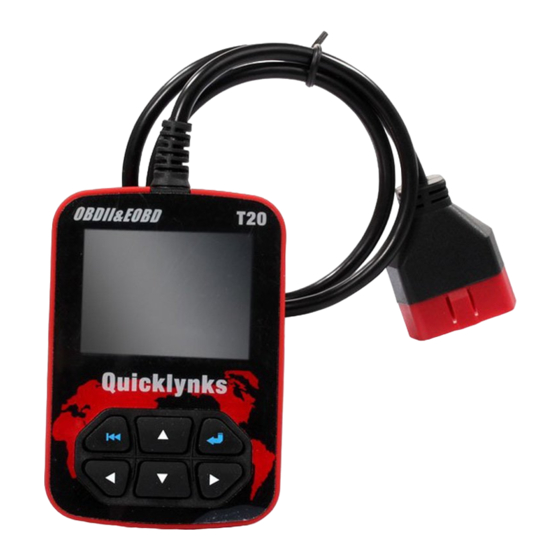
①. Cable with OBD II CONNECTOR -- Connects the AUTO SCANNER to the vehicle ②. LCD DISPLAY -- Indicates test results. ③. ENTER BUTTON--Confirms a selection (or action) from a menu list. ⑤/⑦. RIGHT/LEFT BUTTONs -- Move cursor right or left for selection; Or turn page up or down when more than one page is displayed. -
Page 7: Vehicle Coverage
Press [▲ ] or [▼ ] to select ON/OFF and press [ENTER] to confirm. 3). Time and Date: Set time and date. Choose [Time and Date] and press [ENTER], the screen will display the interface as shown below: Press [▲] or [▼] to change input, press [LEFT] or [RIGHT ] to select position, then press [ENTER] to confirm. 4). -
Page 8: Diagnostic
4.2 Diagnostic Select [Diagnostic] in Main Menu and press [ENTER], the screen will display Monitor Status interface as following Press [ESC] to back to the Main Menu of Diagnostic, the screen will display as following 4.2.1 Read Codes Select [Read Codes] and press [ENTER] in Diagnostic Menu. If there are some codes, the screen will display the codes as shown below: According to the above figure to select different item by pressing [▲] or [▼] and press [ENTER] to confirm. -
Page 9: I/M Readiness
According to the above figure to press [ENTER] and the screen will display the interface as shown on the next page: Notes: ◆ Before performing this function, make sure to retrieve and record the trouble codes. ◆ After clearing, you should retrieve trouble codes once more or turn ignition on and retrieve codes again.If there are still some trouble codes in the system, please troubleshoot the code using a factory diagnosis guide, then clear the code and recheck. - Page 10 As shown the picure above and press [ENTER] button, the screen will display the interface as shown below: Select [View All Items] and press [ENTER] button, the screen will display the interface as shown below You can use [LEFT] [RIGHT] button to view other data streams. Press [ENTER] to return to Diagnostic Menu. Select [select Items] in Data stream menu and press [ENTER], the screen will display the interface as shown below: You can use [▲] [▼] button to select data stream items, and press [LEFT ] [RIGHT] button to turn page, the screen will display the interface as shown on the next page:...
-
Page 11: View Freeze Frame
You can use [▲] [▼] button to select single data stream items to view item of live data with a graph, and press [ENTER] button, the screen will display the interface as shown below: Press [ESC] to return to Diagnostic Menu. You can view all data stream items or select a certain item of live data with a graph. -
Page 12: On-Board Monitor Test
You can use [▲] [▼] button to select an item and press [ENTER], the screen will display as shown below: Press [ESC] to return to Diagnostic Menu. 4.2.7 On-board monitor test This function can be utilized to read the results of on-board diagnostic monitoring tests for specific components/systems. -
Page 13: Code Lookup
4.3 Code Lookup Select [Code Lookup] in the Main Menu and press [ENTER] and the screen will display the interface as shown below You can use [▲] [▼] key to change the first letter. It can be switched among.press [LEFT] [RIGHT] key to input number. After you input the code number, press [ENTER] to view the definition of the code. -
Page 14: Help
Press [ENTER] to confirm, and press [ESC] to return to Main Menu. 5). Delete Data stream The operation is similar to the “elete DTC 6). Delete Freeze Frame The operation is similar to the “elete DTC 4.5 Help This function is used to view Tool Information, About OBD, and About Data stream. Tool Information includes: software version, hardware version, serial number, supported, time and date.
Need help?
Do you have a question about the T20 and is the answer not in the manual?
Questions and answers