Table of Contents

Summary of Contents for Herutu 21D Series
- Page 1 Wired Production Control Indicator Display 21D-429D 21D-265D 21D-485D Instruction Manual V1.90 Please use this Instruction manual correctly on reading well. Please keep it carefully to be able to read immediately, when required.
- Page 2 [21D] Notational Conventions for Series Model Set (Controller +Display) Machine Item Communica Display type LED color types tion 1523 1524 For the Controller only, the contents of 3Communication are as follows: 429C 265C For the Display only, the contents of 3Communication are as follows: 429D 265D 485D...
- Page 3 To use this product in safety and comfort, (Be sure to read) Thank you very much for purchasing our product. This operation manual contains the precautions necessary for preventing an accident caused by the use in an improper ways. Read it carefully while thoroughly understanding the meanings of pictorial symbols. Using in an improper way while ignoring this pictorial symbol might !...
- Page 4 ! Warning ■ For handling this machine: ● Do not use this product for the application needing the high reliability related to human lives. ● Do not use this product in a place where it is uncertain about whether or not radio waves reach.
- Page 5 ※This operation manual is translated a product for Japan into English/ This product is based on Japanese Wireless law.
-
Page 6: Table Of Contents
Contents 1. General Description ........................1 1-1. Scope ............................ 1 1-2. Outline ..........................1 1-3. Machine types ........................1 1-4. Display type ......................... 2 1-5. Communication ........................2 2. Specifications ..........................3 2-1. 3-command type ........................3 2-2. 2-command type ........................4 2-3. -
Page 7: General Description
General Description 1. General Description 1-1. Scope The specifications are applied to the [21D] SERIES wireless production display system. 1-2. Outline The [21D] SERIES wireless production display system consists of the Controller and the Display. Since wireless communication is available between controller and display system, there is no need to make wiring and you can take actions with ease even if layout is changed. -
Page 8: Display Type
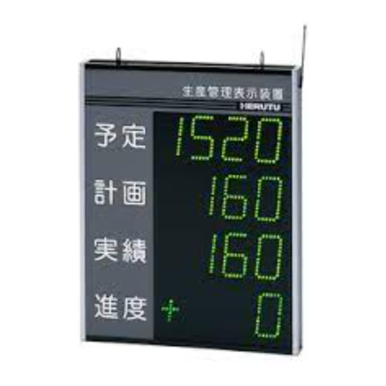
General Description 1-4. Display type The 21D series allows you to select several kinds of display types through the combination of “Target”, “Actual”, “Advancement”, “Accomplishment rate” and “Plan”. You can select the display type of acrylic plate character among the following types. -
Page 9: Specifications
Specifications 2. Specifications 2-1. 3-command type <3-command large-sized type> 21D-3 21DW-3 21D5-3 21D5W-3 Indicator (4-digit x 2-line)+(Symbol+ 3-digit x (5-digit x 2-line) +(Symbol +4-digit x character 1-line) or 4-digit x 3-line 1-line) or 5-digit x 3-line Display surface Single side Double side Single side Double side... -
Page 10: 2-Command Type
Specifications 2-2. 2-command type <2-command large-sized type> 21D-2 21DW-2 21D5-2 21D5W-2 Indicator (4-digit 1-line)+(Symbol+3-digit (5-digit 1-line)+(Symbol+4-digit character 1-line) or 4-digit x 2-line 1-line) or 5-digit x 2-line Display surface Single side Double side Single side Double side Indicator High-luminance 7-segment LED element Character 110H x 60Wmm... -
Page 11: 4-Command Type
Specifications 2-3. 4-command type <4-command large-sized type> 21D-4 21DW-4 21D5-4 21D5W-4 Indicator (4-digit 3-line)+(Symbol+3-digit (5-digit 3-line)+(Symbol+4-digit character 1-line) or 4-digit x 4-line 1-line) or 5-digit x 4-line Display surface Single side Double side Single side Double side Indicator High-luminance 7-segment LED element Character 110H x 60Wmm... -
Page 12: Names And Functions Of Each Section
Names and Functions of each section 3. Names and Functions of each section ②Fitting ①Antenna ③Power cord eject hole ⑨Display section ⑩Side panel(L) ⑧ Screws for removing ⑥Fuse ⑦Acrylic plate ④Power switch acrylic plate(4 pieces on ⑩Side panel (R) both sides) ⑤Power lump 1/4λ... -
Page 13: Setting And Installation Methods
Setting and Installation methods 4. Setting and Installation methods 4-1. Installing the Display Install the Display in a place so that it can be easily seen from the Controller. For the installation in a place with a poor visibility, select an installation site without obstacles near the antenna as far as possible. - Page 14 Setting and Installation methods ②Connect the Power cord. The terminal block for connecting the power source is at back side of display. Slide the acrylic plate at back side to remove the terminal block. Terminal block for connecting the Power cord Side panel(R) Back side Power cord eject hole...
-
Page 15: Connecting The Communication Cable For 485 Communication Type
Setting and Installation methods 4-3. Connecting the Communication cable for 485 Communication type The description in this page is only required when using with the 485 Communication type. The 485 Communication type cannot be used as a set combined with [21D] Series Controller. - Page 16 Setting and Installation methods For the RS-485 line, the terminating resistance should be set at both ends of line. Turn on the terminating resistance for the Indicator unit connected at end using a daisy chain. To turn on/off the terminating resistance, use the jumper switch on the CPU board inside the Indicator unit.
-
Page 17: Setting The Communication Channel
Setting and Installation methods This page and onward describe the setting for the communication (Communication channel and Equipment No.). If you use as a set combined with either of “21D” Series Controller “21D-429C” or “21D-265C”, setting has been completed before shipment. There is no need to make setting stated below. Communication between Controller and Display is only available when the same “Communication channel”... - Page 18 Setting and Installation methods ●429 Communication type Channel No. Frequency(MHz) Channel No. Frequency(MHz) 429.2500 429.5000 429.2625 429.5125 429.2750 429.5250 429.2875 429.5375 429.3000 429.5500 429.3125 429.5625 429.3250 429.5750 429.3375 429.5875 429.3500 429.6000 429.3625 429.6125 429.3750 429.6250 429.3875 429.6375 429.4000 429.6500 429.4125 429.6625 429.4250 429.6750...
- Page 19 Setting and Installation methods ●265 Communication type Channel No. Frequency(MHz) Channel No. Frequency(MHz) 264.500 265.025 264.525 265.050 264.550 265.075 264.575 265.100 264.600 265.125 264.625 265.150 264.650 265.175 264.675 265.200 264.700 265.225 264.725 265.250 264.750 265.275 264.775 265.300 264.800 265.325 264.825 265.350 264.850 265.375...
-
Page 20: Setting The Equipment No
Setting and Installation methods 4-5. Setting the equipment No. Use the DIP Switch on CPU board built in the Display to set the Equipment No. Slide the acrylic plate at front to remove the CPU board at front of Display. Set the Equipment No, which is precisely matched with the contents of the communication format transmitted from the equipment at transmitter. - Page 21 Setting and Installation methods DIPSW 1→ON, 0→OFF DIPSW DIPSW DIPSW DIPSW Equipment No. Equipment No. Equipment No. Equipment No. 1234567 1234567 1234567 1234567 ID000 0000000 ID025 1001100 ID050 0100110 ID075 1101001 ID001 1000000 ID026 0101100 ID051 1100110 ID076 0011001 ID002 0100000 ID027 1101100...
-
Page 22: Operation
Operation 5.Operation If installation and setup of display and controller can be performed, please turn on each power supply. Communication channel and equipment No. is displayed each for 1 second. Display changes the contents received when the date was received from controller. If the display doesn’t receive the data from controller, LED light off the all-points light after 3 seconds turning on. -
Page 23: Applications - Direct Display
Applications 6. Applications - Direct display This article describes the usage when the Controller [21D-429C] is not used. The direct data transmission system to the Display without using the Controller is called “Direct display” in this manual. This function is intended for 429 Communication type and 485 Communication type. (“Direct display”... -
Page 24: Transmitter
Applications 6-1. Transmitter When Controller [21D-429C] is not used, use our wireless modem [TELEMATE III] as the modem for transmitter. Also, when RS-485 communication (wired communication) is conducted, use the RS232C/485 signal converter modem [MODEL485H] as a modem for transmission side. For the detail of [TELEMATE III] and [MODEL485H], see the attached operation manual. - Page 25 Applications Communication format S E B T T C X X C Preamble Dummy data. FFH is added by 5 bytes around. 5 bytes around Start byte (02H) 1 byte Equipment № Indicator unit’s equipment No. “00” – “99” 2-byte “0”...
-
Page 26: Changing The Error Check System
Applications 6-3. Changing the error check system Normally, the error for communication format can be checked according to the aforementioned “Equipment No~ETX’ s CRC-CCITT”, however, it can be changed into “Compare (twice)” system. To change the communication checking system, use the DIPSW “8” on CPU board built in the Indicator unit. -
Page 27: Warranty
Warranty 7.Warranty Provisions of warranty The provisions of warranty are set forth by us for warranty of the product after shipment so that the product can be used with a sense of security after purchased. In case our product is out of order, we will provide repair or replacement under the provisions of warranty. - Page 28 Warranty 8. Troubles occurring due to handling against the use instructions or precautions specified in this operation manual. Initial defects The period within 30 days from the date of shipping the product is defined as the initial defect period for the product. The product will be replaced with a new one or repaired free of charge provided that it is returned to the outlet store through which you purchased the product or our Sales Office, checked, and recognized as having initial defects.
-
Page 29: Dimensional Drawing
Dimensional drawing Dimensional drawing <<3-command large-sized type>> <<3-command middle-sized type>> *The 485D type does not have an antenna. *For the 265D type, the antenna length is different. - Page 30 Dimensional drawing <<2-command large-sized type>> 《2-command middle-sized type》 *The 485D type does not have an antenna. *For the 265D type, the antenna length is different.
- Page 31 Dimensional drawing <<4-command large-sized type>> <<4-command middle-sized type>> *The 485D type does not have an antenna. *For the 265D type, the antenna length is different.
- Page 32 HERUTU ELECTRONICS CORPORATION 62-1 Toyooka-cho, Kita-ku, Hamamatsu, Shizuoka, 433-8103 Japan (Sales dept) TEL.+81-053-438-3555 FAX. +81-53-438-3411 Website URL https://www.herutu.co.jp/en/ E-mail info@herutu.co.jp...
Need help?
Do you have a question about the 21D Series and is the answer not in the manual?
Questions and answers