Advertisement
Quick Links
MODEL 900 PARTS LIST
1
Polar axis assembly (right ascension-R.A.) with stepper drive
1
Declination (Dec.) axis assembly with stepper drive
1
Pier top adapter with six (6) 5/16-18 x 5/8" button head screws with washers
(These will be attached to your pier post if you ordered one)
1
Stainless counterweight shaft with washer stop and black plastic knob (knob has 5/16 thread)
1
Dual axis quartz micro-drive control box
1
"Y" connector cable
1
D.C. Power cord (cigarette lighter adapter on one end)
1
Hex key set
1
Piece of Velcro (to attach hand controller to surface of your choice)
1
Polar Axis Telescope Adapter
In order to fully assemble your mount, you will need the following items separately sold: mounting plate, pier,
counterweights, and portable rechargeable battery pack. Several sizes and types are available for your selection.
Many of these items will be discussed throughout these instructions.
Several additional options will help to enhance your observing experience: Polar alignment scope, JMI computerized
digital setting circles, and Santa Barbara Instrument Group ST-4 or ST-6 CCD Imaging camera/autoguider, trays for
your pier and 12 volt rechargeable battery.
INTRODUCTION
We recommend that you familiarize yourself with the
assembly and basic operation of the mount indoors.
The temperature will be comfortable, the mosquitos at
bay, and you'll have enough light to see the illustrations
and read the manual. Please take particular note of
counterbalancing, use of the clutches and operation of
the hand controller.
WHY POLAR ALIGN?
If you were to take a long exposure photograph with
Polaris (often called the North Star) in the center of the
field, you would discover that all stars seem to revolve
around Polaris. This effect is due to the rotation of the
earth on its axis. Motor driven equatorial mounts were
designed to compensate for the earth's rotation by
moving the telescope at the same rate and opposite to
the earth's rotation. When the polar axis of the
telescope is pointed at the celestial pole (polar aligned)
as shown in the diagram to the right, the mount will
follow (track) the motions of the sun, moon, planets,
and stars. As a result, the object that you are
observing will appear motionless as you observe
through the eyepiece or take astrophotos.
For visual observation, a rough sighting of Polaris
through the hole in the polar axis is fine. However if
astrophotography is your goal, accurate polar
alignment is critical.
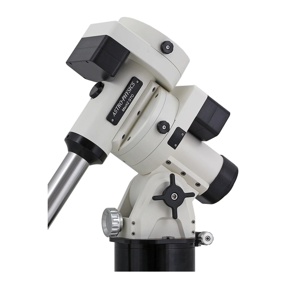
ASTRO-PHYSICS
MODEL 900 GERMAN EQUATORIAL WITH
DUAL AXIS QUARTZ MICRO-DRIVE (900QMD)
- 1 -
Advertisement

Related Manuals for ASTRO-PHYSICS 900


Summary of Contents for ASTRO-PHYSICS 900
- Page 1 ASTRO-PHYSICS MODEL 900 GERMAN EQUATORIAL WITH DUAL AXIS QUARTZ MICRO-DRIVE (900QMD) MODEL 900 PARTS LIST Polar axis assembly (right ascension-R.A.) with stepper drive Declination (Dec.) axis assembly with stepper drive Pier top adapter with six (6) 5/16-18 x 5/8” button head screws with washers...
- Page 2 ASSEMBLY INSTRUCTIONS Please read all instructions before attempting to set up your 900 mount. The Model 900 is very rugged; however like any precision instrument, it can be damaged by improper use and handling. Please refer to the diagram below for an illustration of the mount.
-
Page 3: Before You Leave Home
There are a few simple things that can be accomplished in the comfort of your home before heading outside. GROSS LATITUDE ADJUSTMENT: The latitude range of the 900 mount is approximately 20-68 degrees. Since most astronomers typically observe within one latitude range, this adjustment is made just once, if at all. Prior to shipment, we preset the mount to your latitude range for your convenience. -
Page 4: Assemble Polar Axis Assembly To Pier Or Tripod
10. Firmly tighten both polar axis pivot screws with the hex key. ATTACH PIER ADAPTER TO PIER POST: If you purchased the pier from Astro-Physics, the pier top adapter of the 900 is already attached to the top of the pier. If you are constructing your own pier or tripod, you will need to incorporate this part. -
Page 5: Altitude And Azimuth Adjustments - Rough Polar Alignment
Please continue to read these directions anyway, since you may need to remove and reinstall the encoders if you use a polar alignment scope. The 900 mount is always supplied with the encoders installed. - Page 6 each side of the mount, to make fine adjustments in azimuth. You must back off the opposing azimuth knob in order to move the other knob in that direction. Please refer to the following diagram. 4. Altitude (latitude) adjustments: Loosen the altitude locking knobs. Move the polar axis up or down with the large altitude adjustment knob located in the front of the polar axis assembly.
-
Page 7: Fine Polar Alignment
2. How can you find out what they really do? As shipped, all 900 mounts have all four R.A. and Dec. clutch knobs firmly hand tightened. This will give you a good idea of the maximum tightness (clutch action) that can be achieved by hand effort alone. At this point, you must bear in mind that for optimum performance all four clutch knobs on each axis (R.A. - Page 8 Now, if you proceed to mount up and balance your telescope, you can “feel” what this resistance in R.A. and Dec. (movement backwards and forwards) is like when you make these motions from the eyepiece end of your telescope as you would during normal use when slewing (pushing) by hand to acquire an astronomical object within the field of view of your finder or scope 3.
- Page 9 110 volts with a minimum output of 800ma. at 12VDC. DRIVE ROTATION: If you are operating the 900 mount north of the equator, the HEM (hemisphere) switch must be set to “N”. If south of the equator, set the switch to “S”.
- Page 10 PUSH BUTTONS: The four red buttons are arranged so that the left and right buttons control the movement in right ascension, and the top and bottom buttons control the declination. This is the normal orientation of objects in the eyepiece field. If the star moves down when you push the “N” button, move the DEC REV (Dec. Reverse) switch into the opposite position.
- Page 11 LED KNOB: There is an LED output available on the 900 Dec. axis motor housing as shown in the diagram on page 2. You may insert your LED reticle to this plug. Brightness can then be controlled using the MIN to MAX (minimum to maximum) setting of the LED knob.
- Page 12 Your 900 mount is a precision instrument with very accurate worm and wheel adjustments. Please be careful if you place the mount on a flat surface, i.e. the ground or trunk of your car. The gear alignment may be affected if the R.A.
Need help?
Do you have a question about the 900 and is the answer not in the manual?
Questions and answers