Advertisement
Quick Links
MPG-2
Premium Solid State
Power
Input
2
1
N
7
2
E
7
0
U
V
V
USB Programming
Port
Zigbee USB
R
G
E
R
F1
F2
D
N
Y
K
Z
Y
1
1
1
2
1/10
1/10
Out 1
Out 2 EOI
Amp
Amp
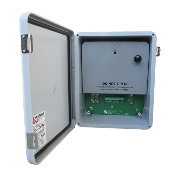
MOUNTING POSITION - The MPG-2 may be mounted in any position but is intended to be mounted with the
hinged door on the left such that the circuit board is upright. The MPG-2 must be mounted within 25' line-of-site of
the meter. Actual operational distance may vary with building construction and ability for the RF signal to penetrate
building materials. For best results, mount the MPG-2 as close to the meter as reasonably possible.
POWER INPUT - For 120VAC, connect 120VAC "hot" lead to the 120V terminal. Connect the neutral wire to the
NEU terminal. For 208 to 277VAC, use the 277V terminal for the "hot" lead and the NEU terminal for the neutral
power supply lead. The EGND terminal MUST be connected to the power supply ground. If the MPG-2 is mounted
at the meter and powered from the meter potentials, AND no true neutral exists at the meter, connect the EGND
and NEU terminals to the electrical system ground.
ZIGBEE WIRELESS COMMUNICATION - The MPG-2 is designed to receive power monitoring information from
an electric meter equipped with Zigbee wireless communications. The Zigbee transceiver dongle is mounted on
the MPG-2's circuit board and may be secured with a tyrap. Ensure that the dongle is properly seated in the USB
host socket. Do not remove.
CUSTOMER OUTPUTs - The customer's outputs are located at the bottom of the MPG-2 board in the customer
compartment. There are two KYZ Form C (3-wire) dry-contact outputs for watt-hour pulses, and one End-of-
Interval (EOI) KY Form A (2-Wire) pulse output. The two 3-wire isolated pulse outputs are provided on the MPG-2,
with output terminals K1, Y1 & Z1 and K2, Y2, & Z2. The End-of-Interval pulse output uses terminals T1 & T2.
Transient suppression for the contacts of the solid-state relays is provided internally. The output loads should be
limited to 100 mA at 120 VAC/VDC with maximum power dissipation of each output limited to 800mW.
FUSES - Fuses are 3AG fast-blow type. One-fourth (1/4) Amp fuses (the maximum size) are supplied
standard. The KYZ outputs for Output1 and Output 2 are protected by fuses F1& F2, respectively. The EOI
output is protected by fuse F3.
OPERATION - See the following pages for a full explanation of the operation of the MPG-2.
Revision: 9/25/2020
ZIGBEE PULSE GENERATOR
INSTRUCTION SHEET
Dongle
Y
E
F3
L
LED's
K
Z
T
T
2
2
1
2
1/10
Amp
SOLID STATE INSTRUMENTS
a division of Brayden Automation Corp.
6230 Aviation Circle, Loveland, Colorado 80538
Phone: (970)461-9600 Fax: (970)461-9605
E-mail:support@solidstateinstruments.com
Firmware Version 2.19
POWER CONNECTIONS
(For 120VAC)
USB Host Socket
for Zigbee Dongle
CUSTOMER'S TERMINALS
UTILITY
COMPARTMENT
CUSTOMER
COMPARTMENT
P/N: 05910-97006E
Advertisement

Related Manuals for SSI MPG-2

Summary of Contents for SSI MPG-2
- Page 1 MOUNTING POSITION - The MPG-2 may be mounted in any position but is intended to be mounted with the hinged door on the left such that the circuit board is upright. The MPG-2 must be mounted within 25' line-of-site of the meter.
- Page 2 MPG-2 Wiring Diagram MPG-2 Wireless Pulse To Line Generator Relay Wireless Data - 25' max Zigbee dongle Host Port Service Entrance Out 1 To EMS Electric Meter w/Zigbee Radio Out 2 To SCADA To Loads 120-277VAC Power Supply Connections MPG-2W iringDiagram.vsd REVISIONS Brayden Automation Corp./...
- Page 3 Hardware Installation - Once you are confident that the MPG-2's Zigbee transceiver is paired with the meter, completing the installation of the physical unit is the next step. If the utility is doing the MPG-2 installation and they are experienced in provisioning, then the Provisioning process may be done after installation. Installation includes mounting the unit at or near the electric meter and connecting the outputs to the destination (pulse receiving) devices.
- Page 4 MPG-2. It must be within 75' but distances may vary depending on whether the radio signal must go through any walls and the material of those walls. For best results mount the MPG-2 as close to the meter as possible with an unobstructed line-of-sight with the meter if possible.
- Page 5 Assuming that the dongle is paired (correctly) with the meter, is on, and is within 75' of the meter, then every 8 to 10 seconds, you will see information similar to the listing below received from the MPG-2. Click on the Monitor box to enter...
- Page 6 The output pulse value is the number of watt-hours that each pulse is worth. This is represented by the Pulse Value field. The MPG-2 can be set from 1 Wh to 99999 Wh per pulse. Select a pulse value that you think will be appropriate for your application.
- Page 7 KYZ 3-Wire electric meter output. It toggles back and forth, to the opposite state, each time a "pulse" is generated by the MPG-2. Even though there are three wires, it is common to use K and Y, or K and Z, for many two-wire systems that require or desire a generally symetrical 50/50 duty cycle pulse.
- Page 8 To enable the filter mode select Enable in the Filter field. Hit "Send". The serial link on the MPG-2 will return the following: ----------------------------------------...
- Page 9 Setting the Real Time Clock The MPG-2 allows the user to set the internal real time clock (RTC) with an initial time using the K command. Once the time is set, the time will elapse until the 2nd data packet is received from the dongle, usually about 30 to 60 seconds after startup.
-
Page 10: Operation
If the dongle is reliably receiving data from the meter and passing it on to the MPG-2's processor, then you should see the Red and Green output LED's toggle each time the selected pulse value is reached, and the MPG-2's processor generates a pulse. - Page 11 WORKING WITH THE MPG-2 RELAY PULSE OUTPUT MODES: The MPG-2 Meter Pulse Generator allows the outputs to be configured in either the "Toggle" or "Fixed" pulse output mode. In the Toggle mode, the outputs alternate or toggle back and forth each time a pulse is generated. This is synonomous with the classic 3-Wire Pulse metering and emulates the SPST KYZ switch model.
- Page 12 To enter the functional or operational mode into the MPG-2, use the Pulse Mode field. Select Normal to set the MPG-2 in the Normal mode. Hit "Send". Select Signed to set the MPG-2 in the Signed mode. Hit "Send". The serial link to the MPG-2 will return "Signed".
- Page 13 Here is a list of the available commands if you are using an ASCII terminal program instead of the SSI Universal Programmer software. If you don't remember them use the help, 'h', 'H', or '?' to bring up the list.
- Page 14 List of MPG-2 Commands EOI Interval Length 'iX<CR>' or 'IX<CR>' - EOI Interval Length, minutes - 1 to 60 minutes, 15 min. default; EOI Interval Length Selections: 'i1<CR>' or 'I1<CR>' - 1 Minute Interval 'i2<CR>' or 'I2<CR>' - 5 Minute Interval 'i3<CR>' or 'I3<CR>' - 10 Minute Interval...
Need help?
Do you have a question about the MPG-2 and is the answer not in the manual?
Questions and answers