Table of Contents
Advertisement
Quick Links
Advertisement
Table of Contents

Related Manuals for TimeTec FingerTec Face ID 4 FMM

Summary of Contents for TimeTec FingerTec Face ID 4 FMM
- Page 1 Face ID 4/4D FMM User Guide...
- Page 2 Timetec Computing Sdn Bhd. Every pre- consequences of anything, done by any such caution has been made to supply complete person in reliance, whether wholly or partially, and accurate information. Information in...
-
Page 3: Table Of Contents
Contents Chapter 4 15-23 Chapter 1 5-6 INSTALLATIONS & CONNECTION GETTING STARTED Installations Viewing the User Guide in the Internet • Mount On Wall Accessories Communications Printed Materials • USB Port Activating Terminal • TCP/IP Port Registering Terminal • Power Supply Port • Access Control Port Chapter 2 7-9 • External Alarm Port BASICS • COM Key Introduction to Terminal Configure TCP/IP connection Terminal Overview Configure USB Flash Disk Main Menu • Download Battery • Upload • External power supply • Download Option Cleaning Terminal Configure WiFi • Cleaning The Body Configure Cloud Server Restarting and Resetting Terminal Connecting The Terminals to TCMS V3/Ingress... - Page 4 Chapter 5 24-28 Chapter 9 38-39 SYSTEM SHORT MESSAGE DISPLAY Setup Date and Time Add a Short Message • To use Daylight Savings Time (DLST) • Select Message Type Attendance Record Storage Option Public, Personal and Draft List • Duplicate Punch Period Message Option • Camera Mod 8 • Display User Photo Chapter 10 • Attendance Log Alert WORK CODE • Cyclic Delete ATT Data Adding a Work Code • Cyclic Delete ATT Photo All Work Codes • Confirm Screen Delay(s) Work Code Options • Face Comagrison Interual • Expiration Rule Chapter 11 Face Options DIAGNOSTIC Reset Options Chapter 12 Chapter 6 29-32 SYSTEM INFO PERSONALIZATION Device Capacity User Interface Device Info...
-
Page 5: Getting Started
Chapter 1 Getting Started Viewing the User Guide in the Internet The User Guide is available in the package when you purchased the terminal. The User Guide is also available online at http://www.fingertec.com and http://user.fingertec.com. Choose the language that you prefer for your User Guide. Terminal Included Accessories Connection Wires Metal Back Plate Screwdriver DC 12V Power Adapter *Face ID 4d only A Packet of Measurement Tape Screws and Bolts Stylus USB Extension RFID Cards (5 pieces) ITEM FUNCTION Metal Back Plate Secure this plate on top of the rubber cushion and place the terminal onto it. -
Page 6: Activating Terminal
Activating Terminal Every FingerTec Time Attendance and Access Control model comes bundled with a unique license key. To start using the terminal with TCMS V3 (for Face ID 4) or Ingress (for Face ID 4d), you must connect the terminal to the software and perform online activation. The software reads the serial number of your terminal and sends it for verification at the Fin- gerTec server via Internet. In case you do not have an Internet connection, you would need to do an offline activation. Please send the serial number and models of your terminals to support@fingertecaustralia.com.au to request for a product key. Registering Terminal Make sure that you register your Face ID 4d warranty with us at https://www.fingertec.com/ver2/english/e_warranty.htm... -
Page 7: Basics
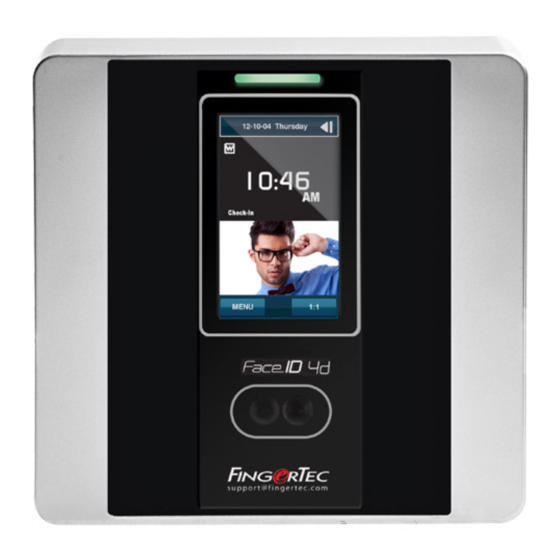
Chapter 2 Basics Introduction to Terminal Introducing Face ID 4, the new facial recognition technology product combined with card technology. Face ID 4 can identify an identity in split seconds without any con- tact or hassle. It only requires a user to look at the machine to get verified. Face ID 4 is loaded with powerful microprocessor that can process facial authentication method for accurate personal identification and for collection of precise data for time attendance and door access* (Face ID 4d only). In addition, the Face ID 4 terminal accepts card veri- fication as an added security measure. If you are looking for a contactless, hassle free biometrics product, choose Face ID 4. With one look you are good to go! Terminal Overview LED Light Indicator Touch Screen LCD Twin Face Camera Card Induction s u p p o r t @ f i n g e r t e c . -
Page 8: Main Menu
Main Menu User Mgt Access Control Enroll users/ manage user data. Configure door access settings in ter- minal. USB Manager User Role Upload and download data and infor- Assign privilege to users for data secu- mation to and from FingerTec terminal rity. -
Page 9: Cleaning Terminal
Cleaning Terminal Cleaning The Body Use a dry cloth to clean the terminal’s body. Do not use any liquids, household cleaners, aerosol spray, solvents, alcohol, ammonia and abrasive solutions to clean the body of the terminal because it could damage it. Restarting and Resetting Terminal If something isn’t working right, try restarting or resetting the Face ID 4. Restarting the Terminal At the bottom of Face ID4, look for the Restart button use a pin, press the button once to restart the terminal. Resetting the Terminal Go to Menu > Data and click on Restore to Factory Settings. Press Yes to confirm. Resetting of Face ID 4 will cause all your settings to return to the original factory settings... -
Page 10: Users
Chapter 3 Users Introduction FingerTec devices recognize users by face recognition, card access or a set of pin num- bers. The Date, Time Data and User ID will be stored in its internal storage upon verifica- tion and will be used to generate reports in accordance with the user’s attendance. Privileges can be assigned accordingly based on individual permissions. Likewise, a Sys- tem Administrator can have his rights restricted or be given full control. Access controls such as the ability to modify settings within the menu will be barred when a System Ad- ministrator has been assigned to a device. The role of an administrator plays a crucial role in the vitality of the data in these devices. For example, Network Administrator(s) can be allowed to configure communication set- tings but not to enroll new users. Three levels of authority govern each device: • Super Administrator The top of the hierarchy, Super Administrators have, full access to all functions. • Administrator The rights of an Administrator are limited by the permissions granted by the Super Ad- ministrator. For example, a Network Administrator can be allowed to configure commu- nication settings but are not allowed to enroll users. • User Normal users have no access to any functions within the device. By default, every user enrolled is a normal user. Super Admin and Administrator roles are allocated from the list of normal users, either directly from the terminal or assigned via our software. -
Page 11: Voice Message
Voice Message VOICE / MESSAGE WHAT DOES IT MEAN? Identity verification is successful, the terminal stores the transaction logs and “Verified” opens the door (if connected to door access) You are not an administrator of the system and you cannot access Menu page. “Admin Affirm”... -
Page 12: Password Enrollment
S tep 3: Select Card > Wave card at the induction area > Screen displays the card ID > Press OK to save S tep 4: Press User Role > Select Role > Select Normal User > Press OK to save Select Super Admin or other defined role(s) you wish to assign to this user. Refer to page 13 for more details regarding User Role Password Enrollment Password verifications have a lessened security presence in Attendance Reporting and Access control systems. Despite this, passwords are generally the primary preference for enrollment. FingerTec devices can accept up to 8-digit passwords in numeric format. Follow the steps below to enroll password: S tep 1: Press Menu > User Mgt > New User S tep 2: User ID > Key in User ID This is the unique ID number that represent the user in the devices and software. Make sure you do not use an existing ID. The maximum length is 9 digits S tep 3: Select Password S tep 4: Insert password for the 1st time > Press OK > Re-enter the password to con-... -
Page 13: Delete User
Delete User Only an administrator can perform user deletion at the terminal. To delete user(s): S tep 1: Press Menu > User Mgt > All User > User ID S tep 2: Key in User ID > Press OK Button > Select Delete S tep 3: Select Delete User, User Role, Fingerprint or Password S tep 4: Press OK Button to delete > Select OK to confirm deletion > ESC to exit. Display Option Users can choose the display style of their credentials either to be in. Single Line, Mul- tiple Line & Mixed Line. The different types of display are shown below: Press Menu > User Mgt > Display Style > Select the type of Display > ESC to Exit SINGLE LINE MULTIPLE LINE MIXED LINE User Role Employees with Super Admin rights are granted limitless access to all settings and sys- tems within the terminal in addition to the ability to enroll new users. Super Admin can also perform system Reset. -
Page 14: Defined Role
Define Role You can define what the administrator is allowed to do at the device. A maximum of three different role sets can be configured. For example, you create a role called Network Admin, and limit his access to the Network option only. Therefore, he is unable to enroll new users or configure device settings. To set the define user role: S tep 1: Press Menu > User Role S tep 2: Select User Defined Role > Press OK > Press OK again to enable the selected Role S tep 3: Rename the Role > Define User Role > Save and Exit. Once these roles have been defined, they will appear in the Users tab where you can assign employees accordingly. Assign Role To define roles for new employees: S tep 1: Menu > User Mgt > New User > User Role S tep 2: Select the role to assign to the employee > Save and Exit. -
Page 15: Installations
Chapter 4 Installations & Communication Installations FingerTec terminals offer several connections for power and communications. Installa- tions of FingerTec time attendance terminals are simple. Mount On Wall Back Plate s u p p o r t @ f i n g e r t e c . c o m 4 feet / 1.2 meter (recommended) • After measuring the height accordingly and make relevant marking on the wall, drill the screws into the wall to secure the back plate. - Page 16 For access control, Face ID 4d POWER SUPPLY (A) GND DC12V 3A Power Supply +12V Alarm output Door Lock System TCP/IP Port CONNECTOR PINS DC12V 3A This is only available Power Supply for Face ID 4d TCP/IP For NC (normally close) door lock system DC12V 3A Alarm Device Alarm Device (NC) (NO) GND 12V NC1 COM1 EM Lock (NC) SEN GND BUT NO2 COM2 NC2 Door Emergency...
-
Page 17: Usb Port
USB Port Linking with USB flash disk for remote data transfer. TCP/IP Port Connect with CAT 5 cable for LAN connection, one end to this port and another end to the computer’s TCP/IP Port. FRONT TCP/IP for Single Connection – Linking the ter- minal to a single computer using TCP/IP re- JOINT 1 PIN JOINT 2 PIN quires Ethernet 10/100Base-T Crossover Cable. -
Page 18: Com Key
We recommend that you delete the attendance records upon completion of the down- load process. The deletion process can be done manually at the device or commands via the software’s interface. This chapter will provide instructions to guide you in setting up the correct parameters to establish connection between your devices and the software. The available communica- tion methods are listed below: • TCP/IP • WiFi (Wireless)* • Cloud Server • USB drive *This communication method is only available upon request Configuring your Device ID should be your first step before continuing with the above communication methods. It is crucial that each terminal’s unique ID is identified and set apart. By default, all our Device IDs are set to “1”, therefore you must change the Device ID manually if multiple devices are installed. To change the Terminal ID: S tep 1: Menu > Comm. >... -
Page 19: Configure Tcp/Ip Connection
Conf igure TCP/IP connection Internet Protocol (IP) is a unique numeric designation of each device within a network. Without an assigned IP Address, it would make identifying a specific terminal difficult. The default IP address of each terminal is 192.168.1.201. Connect your terminal via a RJ45 (LAN cable) to connect to your local area network. To change the IP address: S tep 1: Menu > Comm. > Ethernet > IP Address > OK S tep 2: Insert the IP Address > Press Down arrow to go to the next column See below to understand every column. • IP Address: Known as Internet Protocol Address, the default configuration is 192.168.1.201. -
Page 20: Upload
To download the data: Go to Menu > USB Manager > Download You can select the following data type to copy into the USB drive: • Download Attendance Data: Download attendance data. • Download User Data: Download employees’ data (face/fingerprint templates, pass- word, card ID, names). • Download User Portrait: Download employees’ photos. • Download Attendance Photo: Download photos captured while an employee is suc- cessfully verified. The photos are in JPEG format. • Download Blacklist Photo: Download the photo (captured while employee fails to verify at the device) into USB device. The photos are in JPEG format. • Download Work Code: Download the work code ID. • Download Short Message: Download the short message. Upload Uploading is the process of copying data from a USB drive into a device. The data has to be copied from the software to the USB Drive. To begin uploading your data, connect the USB to your device To uploading the data:... -
Page 21: Configure Wifi
Conf igure WiFi A wireless connection (WiFi) is an available hardware feature in some FingerTec devices. You can link up your devices with the software via a wireless connection. To configure the WiFi connection: S tep 1: Menu > Comm. > Wireless Network > OK to enable WiFi connection > ESC to Save and Exit. S tep 2: Wait for the device to scan the SSID of your WiFi network. S tep 3: Select the SSID of the WiFi network > OK to confirm S tep 4: Insert the WiFi password > OK to confirm S tep 5: Select to use DHCP or Manual assign IP S tep 6: ESC to return to the main menu S tep 7: The WiFi icon appears on the main menu Conf igure Cloud Server FingerTec Webster is a web storage application for managing content that are sent from your devices. The contents include information pertaining to user verification creden- tials, transaction logs and device settings. You will be required to assign an IP address to the server to connect all devices via an Internet connection. The public IP address must be entered into the device to allow a connection. -
Page 22: Connecting The Terminals To Tcms V3/Ingress
• Server Port: Webster’s server port number • Enable Proxy Server: If you choose to enable this function, you must set the IP address and port number of the proxy server. You may choose to enter the proxy IP address of your proxy server for Internet access. Connecting The Terminals to TCMS V3/Ingress Every FingerTec time attendance and access control model comes bundled with a unique license key. To start using the terminal with TCMS V3 (for Face ID 4) or Ingress (for Face ID 4d), you must connect the terminal to the software and perform online ac- tivation. The software reads the serial number of your terminal and sends it for verifica- tion at the FingerTec server via Internet. In case you do not have an Internet connection, you need to do offline activation. Please send the serial number and model of your terminal to your local reseller or support@fingertec.com to request for a product key. -
Page 23: Using Tcp/Ip
Using TCP/IP IP address is important, as it is a unique address of the terminal in LAN. Without the IP address, locating the specific terminal is not possible. To input the IP address of the terminal: S tep 1: Press Menu > Comm. > OK to Enter S tep 2: Ethernet > IP Address > Key in IP Address Setting Up Netmask and Gateway Determining the Netmask, Gateway and NetSpeed: For TCP/IP connection, please con- figure the netmask, gateway and netspeed for the terminal. Setting Up Netmask S tep 1: Press Menu > Comm. S tep 2: Ethernet > Subnet Mask > Insert the numbers. Setting Up Gateway S tep 1: Press Menu > Comm. - Page 24 Chapter 5 System FingerTec devices can be personalised according to preference. These settings include date/time, storage of in-out records and biometric verification rules. You can find the Reset option which allows you to program your devices to default factory settings, un- der this chapter. Setup Date and Time The Date & Time is a very crucial aspect for accurate logging of attendance and the record of door activity in each company. The date and time of the terminal will be dis- played at the home screen. You can choose the date and time format based on your preference.
- Page 25 To use Daylight Savings Time (DLST) Daylight saving time (DLST) is the practice of temporarily advancing clocks so that the daylight in the afternoon will be longer whereas morning will be shorter. Please disre- gard this if DLST does not apply to your country. To set the DLST settings: S tep 1: > Date & Time > Daylight Saving Time > Press Menu > System Press OK to enable S tep 2: Select Daylight Saving Mode > Select either By date/time or By week/day > Configure details in Daylight Saving Setup By Date/Time: This option is recommended if you know the exact date the DLST begins. For example, if company A wants to set the DLST to begin from May 3rd 22:15 hour and ends on July 10th 11:15 hour, this setting should be chosen. S tep 1: Set the month and date for the DLST to begin S tep 2: Set the time (in HH.MM format) on when the DLST will begin. S tep 3: Set the month and date for the DLST will end. S tep 4: Set the end time of the DLST period.
- Page 26 Attendance Record Storage Option Each time a verification is performed on the device, a transaction log will be stored inside the terminal. These logs need to be managed to maintain the effectiveness of the devices. However, you can only setup rules to control attendance capturing and storage. Press Menu > System > Attendance > Select type of rules to configure Duplicate Punch Period (m) In the event that you want to consider all clocking activities within the predefined time interval as a single clocking, you can use this setting. For example, if the IN time is 9:00am and the time interval is 15 minutes, any verification done by the same ID within the 15 minutes will be considered as a same record, taking the first time he/she clocks in. The maximum number of minutes that can be entered is 60. Press the number button to insert the value. Camera Mode You can set the device to take and save photos in verification • No Photo: No Photo is taken during user verification • Take Photo, no save: Photo is taken but not saved during verification • Take Photo and save: Photo is taken and saved during verification • Save on successful verification: Photo is taken and saved during verification • Save on failed verification: Photo is taken and saved during failed verification Display User photo You can set the device to display a photo of the employee after a successful verification. A success verified indicator will appear on the screen after his/her ID and name has been verified. You can transfer photos from the software to the device. This should be enabled if you would like the device to display the employees’ photo on screen. Attendance Log Alert You can set the device to prompt an alert message on screen every time it verifies an employee when its storage is approaching the limit. The value ranges from 1 to 99 (trans- action counts). The device will always delete earlier records to free up space to save the latest record (FIFO, first in first out), if storage is full. By default, the value is 99. Change it...
- Page 27 Cyclic Delete ATT Data You can set the device to delete a number of records when its storage is full. The value range is from 1 to 999 records. For example, you can set the value at 500 records and the device will delete the first 500 records to free up the space to store new records. Cyclic Delete ATT Photo You can set the device to delete a number of stored photos when its storage is full. The value range is from 1 to 99. For example, you can set the value to 50 and the device will delete the first 50 photos to free up slots to store new images. Confirm Screen Delay(s) You can set the time delay for the device to display verification results (ID, name and photo). The time range is from 1s to 9s. Face Comparison Interval Set the facial template matching time interval as per required. Valid value ranges be- tween 0-9s. Face Settings Setting Threshold Threshold is a level of infrared scanner’s sensitivity. Threshold determines how many percent of your face is being read by the system. The higher the threshold level, the more percentage is being read, the more restricted the system. Configure the threshold for 1:1 and 1:N methods.
- Page 28 Reset Options In an event you want to restore the terminal back to the factory settings. To reset options setting: Menu > System > Reset > Press OK. A confirmation window will prompt you before the terminal is reset. Ensure that you are certain of performing the task before proceeding to avoid irreversible data loss.
- Page 29 Chapter 6 Personalization You can manage the display style of your FingerTec device according to your prefer- ence. These include the user interface, voice, bell schedules, punch state options, and shortcut key mapping. User Interface The user interface is designed as such so that users can interact with the device. These include the appearance of the device, response time, and the content that is presented to the user. To setup the display of the User Interface: Go to Menu > Personalize > User Interface > Press OK to Enter > Press arrow and OK but- ton to enable or disable the options: • Wallpaper: You can choose which wallpaper to be displayed on the screen • Language: There are 8 languages preloaded into your device. Select the language that fits your environment •...
- Page 30 Voice You can choose to enable or disable the voice prompts, keyboard sound or adjust the volume of the device. To enable or disable the options: Go to Menu > Personalize > Voice > Press OK to Enter > Press arrow and OK button • Voice Prompt: You can choose to disable or enable the voice greetings or feedback during the operations. • Touch Prompt: You can choose to enable or disable the beeping sounds when press- ing on the keys • Volume: You can adjust the volume of the voice greetings/feedback and keyboard beeps Bell You can schedule the device to ring automatically during specific times. This is a re- minder to alert the employees to start/end work, start/end of break time etc. To activate this function, you have to create a new bell schedule: Go to Menu > Personalize > Bell Schedules > Press OK to Enter > New Bell Schedule > Set the option accordingly: • Bell Status: To turn the bell on or off. • Bell Time: Set the time for the bell to ring automatically. • Repeat: Set the bell to repeat on certain days or every day. • Bell Type: You can set for the bell to be triggered from the internal bell or from an external bell that is wired to the device.
- Page 31 Punch State Options In the event you want your employees to press a button to confirm his/her attendance status (for example Check-In, Break starts etc) you will need to set the punch state from your keyboard’s F1 to F8 buttons. Punch State Mode Set the display of the status keys: Go to Menu > Personalize > Punch State Options > Press OK > Punch State Mode > Select one from below: • Off: To disable Status key function. Employees are not required to press any buttons to report their attendance. The screen will not display any Status key • Manual Mode: By default the device does not display any status key. Press the Status Key to view and select your attendance status. The status key will revert to Check-In mode after an employee has reported their attendance. • Auto Mode: The Status Key switches to a specified status according to the predefined schedule. Employees cannot press the key to change their attendance status. He/she can only report attendance according to the predefine schedule. You can set the time under Shortcut Key Mapping. • Manual and Auto Mode: The Status Key switches to specific status according to the predefined time. Employees can verify their attendance without pressing the button.
- Page 32 Shortcut Key Mappings You can assign six shortcuts as attendance or functional keys. On the main interface, when the shortcut keys are pressed, the corresponding attendance status or function interface will display. To shortcut key mappings setting: Go to Menu > Personalize > Shortcut Key Mappings > Press OK to Enter > Select the appropriate key by pressing the down arrow > Press OK to choose the corresponding action Note: When the Attendance Status shortcut key is selected, you can also set the ‘Auto Switch’ parameter (refer to page 37 regarding Auto Mode).
- Page 33 Chapter 7 Data Manager Data stored in the terminal can be utilized to establish management rights or have spe- cific logs removed. To manage your data: Go to Menu > Data Management > Press OK to Enter Delete Data Data stored in the terminal can be deleted within your Data Management function. Be- low is a list of available options in your terminal: • Delete Attendance Data: Delete all attendance records. • Delete Attendance Photo: Delete all employees’ attendance images. • Delete Blacklist Photo: Delete photos of employees’ captured during a failed verifica- tion attempt. • Delete All Data: Delete data related to face & fingerprints templates, IDs, passwords, card ID and attendance records. • Delete Access Control: Delete access control records. *for Face ID 4d only • Delete Admin Role: Removes administrator privileges in your terminal. All employees who had the privilege will identify as a normal user. • Delete User Photo: Delete all photos. • Delete Wallpaper: Delete all saved wallpapers. • Delete Screen Savers: Delete screensavers. Backup Data Losing valuable data can be discouraging and damaging. Our FingerTec terminal(s) of- fer the option of backing up your configurations to a file within the terminal itself, allow- ing for seamless restorations. However you can choose to save the file onto a USB drive to perform restorations on other terminals. To initiate a backup: Go to Menu > Data Management > Press OK to Enter > Backup Data > Press OK to Enter > Select Backup to USB Disk > Select the items to be backup > Backup Start...
- Page 34 Restore Data Restore the data stored in the device or from the USB drive: Go to Menu > Data Management > Press OK to Enter > Restore Data > Press OK to Enter > Select from USB Disk > Select the data to be restored > Start Restore Access control *for Face ID 4D only Access Control options is used to set the Door Lock setting, Time Zone, Holidays and Access Group. Access Control Options settings To set the parameters of the Door Lock and related equipment To setup the Access Control: Press Menu icon > Access Control > Access Control Options • Door Lock Delay(s): This value is the time period for the door to lock again after it un- locks on successful verification. Default value is 10 second and the range is between 1-10 • Door Sensor Delay(s): This function only works if door sensor is available. When a door is not closing for a specified time, the sensor will trigger alarm system. Specify the time of the delay. Default value is 10s, the range is 0-99s. Choose your preference. • Door Sensor Type: There are two types of door sensor available for door access which are Normally Open (NO) and Normally Close (NC). Once a door sensor is available, you have to choose the door sensor type. Default is None.
- Page 35 Time Zone Time Zone is the minimum time period of access control settings, there are 50 Time Zone can be set for the system. Each Time Zone consistof 7 time period section(a week), and each time period section is the valid time for access within 24 hours To setup the Time Zone Press Menu icon > Access Control > Time Schedule Step 1: Tap the input box of Search Rime Zone. Step 2: Enter the number of the time zone (50 in total) to be searched. Step 3: Tap the date on which time zone setting is required. Step 4: Press Up and Down to se the start and end time, then press Confirm (OK) Note: 1. Valid Time Zone: 00:00 ~ 23:59 (Whole day valid) or when the end time is greater than the start time 2. Invalid Time Zone: When the end time is smaller than the start time 3. The default time zone 1 indicates that Device’s Door is open all day long...
- Page 36 Access Group Setting Adding New Access Group Press Menu > Access Control > Access Group > New Group • NO. : Acces Group ID • Verification Mode : Verification type for users in this Group • Time Zone: valid access time for user is this Group • Include Holidays : Enabling this mean this group will use the Holiday’s settings and Time Zone Edit Access Group Press Menu > Access Control > Access Group > All Groups > select Group ID > Edit Delete Access Group Press Menu > Access Control > Access Group > All Groups > select Group ID > Delete Duress Options Press Menu > Access Control > Duress Option Alarm on 1:1 Match Alarm on 1:N Match Alarm on Password Alarm Delay (s)
- Page 37 Chapter 8 Attendance Search The device stores attendance records, which can be processed by our software to pro- duce payroll calculations and other reports. This search function is an easy to use mod- ule that allows you to check and browse records at your convenience at any time. You can choose to display photos together with attendance records. To use this browser: Go to Menu > Attendance Search > Press OK > Insert the user ID to search (leave blank if you want to see all employees) > Press OK > Select the time range from the list or enter specific date and time at the User Defined > Press OK to see all records...
- Page 38 Chapter 9 Short Message Display Displaying public or private short message(s) is a function available on some termi- nals. Private messages will be displayed at the bottom of the screen only after specific recipients have been verified at the terminal. A mail icon at the top of the screen will appear when a message is available. Add a Short Message To enter a short message: Go to Menu > Short Message > New Message > Message > Enter the message > Press OK to save. Note: Press * to display the input method. Press # to enter a space between words. Press Esc to exit the input method. Set the date and time for the Short Message to take effect and expire: S tep 1: Go to Menu > Short Message > New Message > Start Date > Enter the date or press Up/Down Button to select the date > Press OK to Save. S tep 2: Set the start time for the message to begin to take effect. S tep 3: Set the expiry time in minutes for the message to stop appearing in the screen. Range from (1-99 minutes). Note: Public messages will only be available on screen for the time period as configured in your settings . Press OK to acknowledge the message to return back to the menu. Select Message Type There are 3 types of message that you can set it to. • Public: Message is viewable by everyone. • Personal: Message is for designated individuals. • Draft: You can save the message in draft first before assigning them to public or personal at a later time.
- Page 39 > Short Message > New Message > Message Type > Select the preferred Go to Menu message type > Press OK to save. Public, Personal and Draft List View, edit or delete messages in their respective list: Go to Menu > Short Message > Select either Public, Personal or Draft from the list > Select the appropriate actions. Note: The operations of the ‘edit’ function are similar to that of adding a short message Message Option Set the active duration of a message before it is removed from the screen: Go to Menu > Short Message > Message Options > Select the preferred delayed time or define it yourself > Press OK to save.
- Page 40 Chapter 10 Work Code A majority of FingerTec Terminals is incorporated with a feature which allow users to select a reason for re-entry during verification by selecting a work code (for example, work code 13 – Onsite at Customers). Adding a Work Code By default, our terminals does not contain any workcodes. To add a workcode: Go to Menu > Work Code > New Work Code > Key in the workcode • ID: The work code ID supports 1 digit to 8 digits in length. • Name: Short description of the work code. All Work Codes All work codes can be viewed, deleted or edited (with the exemption of modifying the ID number) in the All work codes tab. The process of editing a work code is similar to adding a work code as explained in 10.1. To view all work codes: Go to Menu > Work Code > All Workcodes > Select the Workcode > Press OK to Select either to Edit or Delete the selected Work Code. Work Code Options The option to use work codes must be enabled before it can be utilized. To turn on Work Code: Go to Menu > Work Code > Work Code Options > Work Code Required > Press OK to turn it ON Note: If you wish to bar employees from entering new workcodes during verifi- cation, you must enable the function “Work Code must be defined”. The termi- nal will reject work codes it cannot match to in its current list.
- Page 41 Chapter 11 Diagnostic The Diagnostics page allows you to analyze the condition of your terminal(s) by utiliz- ing a series of tests. Only administrators are authorized to perform these tests. To view the status of your terminal, you can select Go to Menu > Autotest: All Test This option will assess the quality of the terminals LCD Display, Voice, Keyboard and Biometric Sensors. LCD Test This will perform an evaluation test of your terminals’ display by gauging its effects under all colors, including pure white and black. Press OK to continue to the next test or Esc to Stop. Test Voice Select this function to ensure the quality of your voice files are clear and complete. Pressing OK to continue to the next test or Esc to Stop. Test Camera This will determine if the photos taken by the camera are clear and acceptable. Test Clock RTC The RTC test will accurately examine the time & date to ensure the time logged is ac- curate. Click OK to start the test. Every 10ms passed will be displayed as 1s.
- Page 42 Chapter 12 System Info This option allows you to check your terminals storage, firmware, algorithm etc. To access your system information: Go to Menu > System Info Device Capacity The number of enrolled users, administrator, passwords, total fingerprint and attend- ance records will be displayed. Device Info The Device name, serial number, MAC address, Fingerprint Algorithm, Platform Informa- tion, MCU version, Manufacture and Manufactured Date and Time will be shown in this section. Firmware Info The Firmware version, Bio Service, Push Service, Standalone Service and Dev Service is available from this tab.
- Page 43 Troubleshooting “Unable to Connect” Appears When this message appears, it means that the settings for the terminal and the computer are not properly done. Find out which method you are using to con- nect. The terminal offers LAN, RS232, RS485 and USB communication methods. Refer to Chapter 4 to further understand the topic. “Admin Affirm” Appears You are not the administrator of this terminal. Only an authorized administra- tor of the system is allowed to access the Menu. Any attempt of normal user to access the Menu will prompt “Admin Affirm” message on the screen. In case the administrator or he/she has resigned from the company, kindly contact your FingerTec authorized reseller to access the terminal. The LED is Blinking All The Time You have nothing to worry about unless the blinking light is red. The green blink- ing light is indicating that the terminal is under its standby mode. Red blinking light may signal problem in the terminal. Contact your reseller for consultation.
- Page 44 Speaker is damaged Once you have rectified the voice mode, if the problem persists, proceed to test the voice. Go to Chapter 8 to do the test. If no voice is being emitted, contact your local reseller for support. For more troubleshooting, go to http://user.fingertec.com/...
- Page 45 . t i m e t e c c l o u d . c o m © 2021 Timetec Computing Sdn Bhd. All rights reserved.• 022021...
Need help?
Do you have a question about the FingerTec Face ID 4 FMM and is the answer not in the manual?
Questions and answers