Table of Contents
Advertisement
Quick Links
Advertisement
Table of Contents

Summary of Contents for Surface Concept Preamplifier-CFD
- Page 1 1-Channel & 4-Channel Preamplifier-CFD Manual...
- Page 2 Surface Concept GmbH Am Saegewerk 23a 55124 Mainz Germany User Manual for the 1-Channel Preamplifier-CFD R007 phone: +49 6131 62716 0 & 4-Channel Preamplifier-CFD R011 fax: +49 6131 62716 29 Manual Version 2.3 email: info@surface-concept.de web: www.surface-concept.de Printed on 2020-10-20...
-
Page 3: Table Of Contents
Preamplifier-CFD Manual 1 Table of Contents 1 Table of Contents ........................3 2 General Information ........................5 2.1 General Information & Safety Instructions ..............5 2.2 General Overview of the System ..................5 3 CFD - Principle of Operation ....................7 3.1 CFD - Principle of Operation...................7 4 Technical Specification......................9... -
Page 5: General Information
2 General Information 2.1 General Information & Safety Instructions This manual is intended to assist users in the operation of the 1-Channel Preamplifier-CFD R007 and 4-Channel Preamplifier-CFD R011. It is divided into 4 chapters. Surface Concept strongly recommends reading this manual carefully before operating the Preamplifier- CFD. -
Page 7: Cfd - Principle Of Operation
Preamplifier-CFD Manual 3 CFD - Principle of Operation 3.1 CFD - Principle of Operation The technique of the constant fraction discriminator (CFD) is based on summing the original input signal to an inverted signal. The original input signal is delayed but of full height, while the inverted signal is attenuated. -
Page 9: Technical Specification
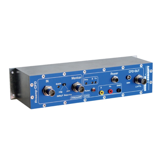
Preamplifier-CFD Manual 4 Technical Specification 4.1 Layout of Front Panel Figure 1: Front Panel of 1-Channel Preamplifier-CFD 5 6 7 12 13 14 Figure 2: Front Panel of 4-Channel Preamplifier-CFD Figure 3: Back Panel of 4-Channel Preamplifier-CFD... - Page 10 1. BNC Input for Negative Analogue Signal 2. Regulator for Variable Gain of Preamplifier 3. Switch for Pulse Input Polarity (neg. or pos.) 4. BNC Monitor Output for Amplified Analogue Signal (Recommendation: use AC-coupled measurement mode when observing the signal with an oscilloscope) 5.
-
Page 11: Input/Output Features
Preamplifier-CFD Manual 4.2 Input/Output Features 4.2.1 Input Features Preamplifier Input Signal: 2mV - 1V (BNC) (depending on gain setting) Polarity of Input Signal: negative or positive (switchable) Impedance: 50Ohm 4.2.2 Output Features CFD Output Signal per Channel: 1 LVTTL (BNC), 1 NIM (LEMO) Pulse Width of Output Signal (typ.):... -
Page 12: Adjustment Of The Asymmetry
6. Minimize the CFD walk for small pulses by adjusting the zero offset. 4.4 Power Requirements The 1-Channel Preamplifier-CFD is supplied by a wall power supply (input: 100 – 240V, 50 – 60Hz, 1.0A max) with a maximum output of 15W (+5V, 3A). -
Page 13: List Of Figure
Figure 1: Front Panel of 1-Channel Preamplifier-CFD..............................9 Figure 2: Front Panel of 4-Channel Preamplifier-CFD..............................9 Figure 3: Back Panel of 4-Channel Preamplifier-CFD..............................9 Figure 2: View of 5 Pin housing connector of 1-Channel Preamplifier-CFD from outside................. 12... - Page 14 Electromagnetic compatibility (EMC): Generic standards - Emission standard for industrial environments EN 61010-1: 2010 Safety Requirements for Electrical Equipment for Measurement, Control and Laboratory Use For and on behalf of Surface Concept GmbH Mainz,……01.04.2013………. Legal Signature………………………………………… (Date) (Dr. Andreas Oelsner) This declaration does not represent a commitment to features or capabilities of the instrument.
Need help?
Do you have a question about the Preamplifier-CFD and is the answer not in the manual?
Questions and answers