Table of Contents
Advertisement
Quick Links
Advertisement
Table of Contents

Summary of Contents for Surface Concept ADD 1.7
- Page 1 ADD 1.7 - Manual 16-fold Frequency Divider ADD 1.7 Manual...
- Page 2 ADD 1.7 - Manual...
- Page 3 ADD 1.7 - Manual All rights reserved. No part of this manual may be reproduced without the prior permission of Surface Concept GmbH. Surface Concept GmbH Am Sägewerk 23a 55124 Mainz Germany Tel. ++49 6131 627160 Fax: ++49 6131 6271629 www.surface-concept.com,...
- Page 4 ADD 1.7 - Manual...
-
Page 5: Table Of Contents
ADD 1.7 - Manual Table of Contents Table of Contents....................................5 Introduction......................................6 2.1 General Information..................................6 2.2 General Overview of the System............................. 6 2.3 Safety Instructions..................................6 Device Layout...................................... 7 3.1 Initial Inspection..................................... 7 3.2 Connector Layout..................................7 3.3 Schematic Layout and Device Functioning......................... 8 3.4 Power Supply.................................... -
Page 6: Introduction
ADD 1.7 - Manual Introduction 2.1 General Information This manual is intended to assist users in the operation of the Frequency Divider ADD 1.7. It is divided into 4 chapters. 2.2 General Overview of the System The ADD 1.7 is a 16-fold frequency divider for digital signals with a LVTTL signal level. The package of the ADD 1.7 includes the ADD 1.7 and an AC-DC adapter with a special 5 pin plug for power supply. -
Page 7: Device Layout
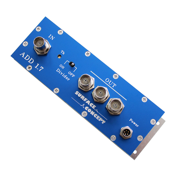
Visual inspection of the device is required to ensure that no damage has occurred during shipping. Should there be any signs of damage, please contact SURFACE CONCEPT immediately. Please check the delivery according to the packing list (see Table 1) for completeness. -
Page 8: Schematic Layout And Device Functioning
3.4 Power Supply The operation power for the ADD 1.7 is +5V. It is provided via a wall power supply. Connect the wall power supply to the round 5pin socket named “power” of the ADD 1.7. The pin configuration of the 5pin socket is shown below in Figure 3. -
Page 9: Technical Data
ADD 1.7 - Manual Technical Data Layout and Performance: No. of Input Channels: Signal Level for Input Signal: Low voltage TTL (but TTL tolerant) Connector Type for Input Signal: No. of Output Channels: 3 (as 3-fold FAN OUT) Signal Level of Output Signal:...
Need help?
Do you have a question about the ADD 1.7 and is the answer not in the manual?
Questions and answers