Table of Contents
Advertisement
Quick Links
Advertisement
Table of Contents

Summary of Contents for MED Associates SG-231
- Page 1 28V DC TO TTL ADAPTER SG-231 USER’S MANUAL DOC-203 Rev. 1.6 Copyright ©2020 All Rights Reserved Med Associates, Inc. P.O. Box 319 St. Albans, Vermont 05478 Phone: 802.527.2343 Fax: 802.527.5095 www.med-associates.com...
- Page 2 This page intentionally left blank...
-
Page 3: Table Of Contents
SG-231 28V DC TO TTL ADAPTER M E D A S S O C I A T E S , I N C . Table of Contents Chapter 1 | Introduction ....................1 Specs: .............................. 1 Chapter 2 | Hardware ..................... 2 Configuration 1 .......................... - Page 4 SG-231 28V DC TO TTL ADAPTER M E D A S S O C I A T E S , I N C . Notes _____________________________________________________________________________________ _____________________________________________________________________________________ _____________________________________________________________________________________ _____________________________________________________________________________________ _____________________________________________________________________________________ _____________________________________________________________________________________ _____________________________________________________________________________________ _____________________________________________________________________________________ _____________________________________________________________________________________ _____________________________________________________________________________________ _____________________________________________________________________________________ _____________________________________________________________________________________ _____________________________________________________________________________________ _____________________________________________________________________________________ _____________________________________________________________________________________...
-
Page 5: Chapter 1 | Introduction
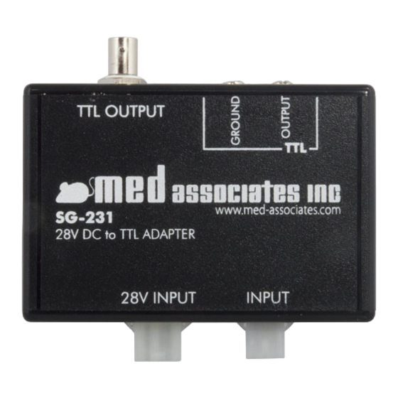
S G - 2 3 1 2 8 V D C T O T T L A D A P T E R CHAPTER 1 | INTRODUCTION The SG-231 is a 28V DC to TTL adapter allows the user to send TTL signals from Med Associates devices such as response levers, head entry detectors, nose pokes, etc. (Configuration 1). -
Page 6: Chapter 2 | Hardware
This configuration allows the user to send TTL signals from a Med Associates device in a standalone or custom application. In this configuration the SG-231 requires an input from a 28V DC power source and a Med Associates device, such as a retractable lever (both sold separately). See Figure below. -
Page 7: Configuration 2
This configuration allows the user to convert the 28V DC signal from an available output on a powered Med Associates Connection Panel to a TTL signal. The SG-231 does not require a 28V DC input in this configuration; the output on the powered Connection Panel supplies 28V DC. See Figure below. -
Page 8: 28V Input Co Nnector
Figure 2.4 - 28V Input Connector Med Inp ut C onnect or Configuration 1 - The INPUT connector is connected to the output of a Med Associates lever, head entry detector, nose poke device, etc. Configuration 2 - The INPUT connector is connected directly to an available output on a powered Med Associates Connection Panel. -
Page 9: Ttl Outputs
NOTE: Place fork lugs between screw head and washer. The optional Med Associates PHM-155G screw terminal to BNC cable makes for convenient connections to most TTL devices and if 2 BNC connections are desired. Figure 2.7 - TTL Ground and Output Screw Terminals - 5 - DOC-203 Rev. -
Page 10: Chapter 3 | Ttl Output Setting
To change the TTL logic jumper to the Active Low (Jumper connecting pins 1 and 2), remove the 2 screws from the bottom of the SG-231, flip over, and lift the top cover off. Near the center of the printed circuit board is jumper location JP1, see Figure 3.1. -
Page 11: Appendix A | Contact Information
S G - 2 3 1 2 8 V D C T O T T L A D A P T E R APPENDIX A | CONTACT INFORMATION Please contact Med Associates, Inc. for information regarding any of our products. For Technical questions, email support@med-associates.com.
Need help?
Do you have a question about the SG-231 and is the answer not in the manual?
Questions and answers