
Subscribe to Our Youtube Channel
Related Manuals for Sifam Tinsley ST 301 ATS

Summary of Contents for Sifam Tinsley ST 301 ATS
- Page 1 GENSET CONTROLLER Automatic Transfer Switch Instruction Manual ST 301 ATS Page 1/44...
-
Page 2: Table Of Contents
INDEX 1- GENERAL REQUIREMENTS AND INSTALLATION ........................3 1- 1 General notes........................................3 1- 2 Dimensions........................................... 3 1- 3 Hardware ratings......................................... 4 1- 4 Electrical Installations......................................5 1- 4.1 Drawing..................................................1- 4.2 Connections................................................1- 5 Operation modes........................................ 7 1- 5.1 Automatic mode..............................................1- 5.2 Manual mode................................................ -
Page 3: 1- General Requirements And Installation
1- GENERAL REQUIREMENTS AND INSTALLATION 1- 1 General notes WARNING! Carefully read the manual before the installation or use. This equipment is to be installed by qualified personnel, complying to current standards, to avoid damages or safety hazards. Before any maintenance operation on the device, remove all the voltages from measuring and supply inputs. Products illustrated herein are subject to alteration and changes without prior notice. -
Page 4: Hardware Ratings
1- 3 Hardware ratings GENERAL CHARACTERISTICS Rated voltage Vdc 12Vdc (24Vdc) Allowed Vdc from 6Vdc to 33Vdc Rated voltage Vac 400 Vac Allowed Vac Up to 500 Vac Allowed frequency From 45 to 75 Hz Max consumption with backlight 250 mA -30 °C + 70 °C (electric) Temperature range -20 °C + 70 °C (display) -
Page 5: Electrical Installations
1- 4 Electrical Installations 1- 4.1 Drawing Warning! Before inserting the plugs and supply the board, make sure that the connections strictly comply with the wiring diagram below. Page 5/44... -
Page 6: 1- 4.2 Connections
1- 4.2 Connections J1 – Genset AC voltage and contactors J4 – Digital inputs 1.1 - Mains contactor output (NC) 4.1 - Gnd 1.2 - Mains contactor output (NC) 4.2 - Gnd 1.3 - Genset contactor output (NO) 4.3 - Gnd 1.4 - Genset contactor output (NO) 4.4 - Programmable digital input (default –... -
Page 7: Operation Modes
1- 5 Operation modes At the power on, the Genset is in reset mode. With the buttons you can choose the functioning mode you prefer. 1- 5.1 Automatic mode Push the AUT button to select this functioning mode. In case of mains failure the remote start output (J5.4) is activated and is de-activated in the presence of the same. This is the standard logic. It’s also possible to activate the remote start output in special conditions. -
Page 8: Equipment Overview
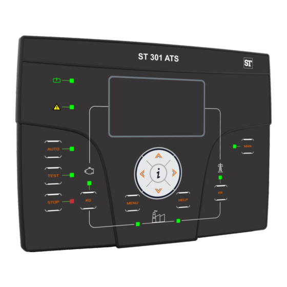
1- 6 Equipment Overview POS. NAME DESCRIPTION Backlighted display that shows all functions, measures and alarms about the generator and the mains. Display Automatically the backlight turns off, and it turns on again when you press a button. Button to select the automatic mode. TEST Button to select the test mode. -
Page 9: Display
1- 7 Display pages 1- 7.1 Navigation diagram When you turn on the board, you will see the logo page. Then you will be in the mains stand-by page. When you start the generator, you will go in the genset stand-by page. When you stop the engine you will return automatically to the mains stand-by page. With the left and right arrows, you can move through the different sections, and with the up and down arrows you can scroll the pages of the selected section. -
Page 10: 1- 7.2 Navigation Cursors And First Activation
1- 7.2 Navigation cursors and first activation The cursors on the upper side and left side of the display indicate the position of the page inside the navigation diagram: the left and right arrows move the page along with horizontal cursor. The left arrow button allows to return back to the previous section: in this case from the generator pages to the mains pages. -
Page 11: 1- 7.3 Display Pages - Mains
1- 7.3 Display pages - Mains 1- 7.3.1 Mains stand-by 1- 7.3.5 Mains 4 When you turn on the board, you will see the logo page. After 5 (shown only in case of 3-phase system) seconds you will be in this page, that is the stand-by page with engine OFF: Mains apparent power L1-L2-L3 and total Mains reactive power L1-L2-L3 and total... -
Page 12: 1- 7.5 Display Pages - Engine
1- 7.4.3 Genset 2 Total work hours of the generator Battery voltage of the generator (shown only in case of 3-phase system) Hours left to service Oil pressure Engine temperature Fuel level percentage Note: this page is shown only if parameter B inside menu M7.1 is set to “Modbus Master”... -
Page 13: 1- 7.9 Clock And Warranty
1- 7.8.3 Expansion inputs Here you can see the state of the 8 digital inputs of the expansion board (only with expansion enabled). 1- 7.8.4 Expansion outputs Here you can see the state of the 8 digital outputs of the expansion board (only with expansion enabled). -
Page 14: Connection Via Rs485 With Genset Controller
1- 8 Connection via RS485 with genset controller It’s possible to connect the ATS with a genset controller via RS485. This way it’s possible to read the most important measures and alarms directly by the ATS controller, and command the starting and stopping of the genset via RS485, without other external connections. -
Page 15: 2- Programming Menus
2- PROGRAMMATION MENUS 2- 1 Navigation chart - Global Setup Direct to Alarm parameters category setup Direct to parameters M6.1 – EJP setup M6.2 – Start by mains kW M6.3 – Dummy load M6.4 – Setup M6.5 – Hour counters Directly to parameters M7.1 –... -
Page 16: Navigation Instructions
2- 2 Navigation instructions Entering global setup, pressing the MENU button, you have to insert the correct password to access to the programming menu. Press the DOWN arrow to highlight the square with the password, and press “i” to confirm. Modify the password with the LEFT and RIGHT arrows, then confirm with “i”. -
Page 17: M1 - Mains Setup
2- 3 M1 - Mains setup RANGE OF DEFAULT POS. NAME DESCRIPTION VALUES SETTINGS Mains rated V Allows you to set the rated voltage of the mains. 0-600 [Vac] You can set the high threshold voltage; if the voltage measured is Mains high V higher than this value (% of the rated voltage), the mains is considered 100-200 [%]... -
Page 18: M2 - Alternator Setup
2- 4 M2 - Alternator setup RANGE OF DEFAULT POS. NAME DESCRIPTION VALUES SETTINGS GE rated V Rated voltage of the generator. 0-600 [VAC] You can set the high threshold voltage; if the voltage measured is higher than GE high V this value (% of the rated voltage), the generator is considered faulty and 100-200 [%] Genset shows the “high GE voltage”... -
Page 19: M3 - Engine Setup
2- 5 M3 - Engine setup RANGE OF DEFAULT POS. NAME DESCRIPTION VALUES SETTINGS It is the time delay from the engine running detection to the enable of the ON alarm delay alarms; this time allows the generator to reach the nominal operating 0-1000 [s] conditions. -
Page 20: M4 - General Setup
2- 6 M4 - General setup The general setup is composed by 4 submenus: Display setup: Submenu that contains all the parameters settings of the screen: language, contrast, etc Clock setup: Submenu with the general settings about the clock: date, time and day of the week Test setup: Submenu with the settings of the test operation mode, like the length and day of the programmable tests Security setup: Submenu to set the passwords for different levels that lock and unlock the various menus 2- 6.1 M4.1 - Display setup... -
Page 21: 2- 6.3 M4.3 - Test Setup
2- 6.3 M4.3 - Test setup DEFAULT POS. NAME DESCRIPTION RANGE OF VALUES SETTINGS Start hour You set the hour of test 1 starting. 0-23 Start min. You set the minute of test 1 starting. 0-59 Test length You set the length time for the test 1. If Off, test 1 is disabled. Off... -
Page 22: 2- 6.4 M4.4 - Security Setup
2- 6.4 M4.4 - Security setup The security setup menu permits to enter the access codes the permit to lock/unlock the programming menus. By default, the access codes are set correctly, so you can access to all the menus. You have the possibility to protect the programming menus entering wrong codes: this way the menus correspondent to the wrong code inserted are locked. -
Page 23: M5 - Alarms List
2- 7 M5 - Alarms list The alarms setup is composed by 4 different alarm groups: Mains alarms Generator alarms Engine alarms General alarms Select the category with the down and up arrows, then press “i” to confirm and enter. You will see a general screen for the setup of the alarms, composed by 4 pages. -
Page 24: 2- 7.1 M5 - Alarms Default Parameters
2- 7.1 M5 - Alarms default parameters Activation Action Category Alarm code Alarm name þ Mains 1208 Mains: low freq. þ þ þ Mains 1209 Mains: high freq. þ þ þ Mains 1213 Mains: V asymmetry þ þ þ þ Mains 20025 Faulty mains... -
Page 25: 2- 7.2 M5 - Alarms Description
2- 7.2 M5 - Alarms description Alarm Menu / Alarm name Alarm description code Parameter 1208 Mains: low freq. Indicates that the mains frequency is under the programmed threshold M1-F 1209 Mains: high freq. Indicates that the mains frequency is over the programmed threshold M1-E 1213 Mains: V asymmetry... -
Page 26: M6 - Special Functions
2- 8 M6 - Special functions The Genset has 5 menus for special functions: EJP, Start by mains kW, Dummy load, TPS, Hour counters. The relative parameters can be set in this menu. The submenus are the following: EJP - only auto mode Start by mains kW (peak shaving) - only auto mode Dummy Load - only auto mode TPS (timer programmable start stop) - only auto mode... -
Page 27: 2- 8.2 M6.2 - Start By Mains Kw
2- 8.2 M6.2 - Start by mains kW Function that allows the generator’s automatic start and stop, according to the maximum and minimum thresholds programmable on mains consumption. If the load consumption from the mains supplies exceeds the START THRESHOLD for a period of time longer then the TIME FOR START, Genset starts the generator and switch the load for the generator. -
Page 28: 2- 8.4 M6.4 - Tps
2- 8.4 M6.4 - TPS This function similar to automatic test is used to program up to two working intervals which activate the generator at chosen clock time and stop it at a chosen clock time. It's also possible to program if the working time is with or without load, with or without remote stop and which are the days allowed to work. -
Page 29: M7 - Connectivity
2- 9 M7 - Connectivity 2- 9.1 M7.1 - Serial port setup RANGE OF DEFAULT POS. NAME DESCRIPTION VALUES SETTINGS Unit ID It’s the address of the board for RS485 communication. 0-255 Protocol types available: None: Serial port disabled. None Modbus Master: used for the connection with RI6010 expansion and Genset Modbus Master Modbus... -
Page 30: 2- 9.2 M7.2 - Gsm Setup
2- 9.2 M7.2 - GSM Setup RANGE OF DEFAULT POS. NAME DESCRIPTION VALUES SETTINGS Status of the modem: initial (initializing phase), wait (waiting), ready (stand-by Modem status phase), send (sending a message), send wait (waiting the response). It enables the automatic status messages and alarm via SMS for SMS app or APP enable On-Off... - Page 31 # DATA SMS SECTION FORMAT DESCRIPION DATA DESCRIPTION CHARACTERS [Message type] Message header for ATS Genset =---------------- =[Generator name] Name of the generator O=AUTO O=[Program] Operative mode active (“OFF“-“MAN“-“AUTO”-“TEST”) ,P=000 ,P=[Active power kW] Total active power M237 M[Mains voltage line 1] Mains L1-n voltage ,237 ,[Mains voltage line 2]...
- Page 32 2- 9.2.2 - SMS commands list This is the list of commands which could be sent to mobile device: TEXT SENT COMMAND NAME DESCRIPTION (case sensitive) MANUAL MODE Activate manual mode on remote device AUTO MODE Activate auto mode on remote device OFF MODE Activate Off...
-
Page 33: 2- 9.3 M7.3 - Datalogger
18000 7940,00 330,83 4,80 21600 9528,00 397,00 4,00 List of logged variables: Generator voltage L1-n (V) Generator voltage L2-n (V) Generator voltage L3-n (V) Generator frequency (Hz) Mains voltage L1-n (V) Mains voltage L2-n (V) Mains voltage L3-n (V) Mains frequency (Hz) Load current L1 (A) Load current L2 (A) Load current L3 (A) -
Page 34: M8 - Io Setup
2- 10 M8 - IO setup The IO setup is composed by 6 submenus: A) Input setup: Submenu that contains all the parameters about the input functions available. B) Output setup: Submenu that contains all the parameters about the output functions available. C) Input type: Submenu to set input types, you can select between disabled, normally open, normally closed or analog if the input allows it. -
Page 35: 2- 10.2 M8.2 - Output Setup
2- 10.2 M8.2 - Output setup The Output setup permits to select the type of use of the programmable outputs. The outputs O5.8, O5.9, O5.10, O5.11, O5.5 and O5.4 can be programmed as: None: no function associated to the output Start: the output is used to command the start of the genset to the engine protection controller Siren: the output is used to command a siren that sounds when an alarm with siren enabled appears Global alarm 1: the output is used to command an indication when an alarm set as general alarm 1 appears. - Page 36 Single alarms ID list: Use the list below in conjunction with M8.2G, M8.2H and M8.2 I parameters to assign a specific alarm to an output. Configuration example: Mains: low freq. M8.2 - b programmed to "ALARM A" Mains: high freq Mains: low voltage M8.2 - c programmed to "ALARM B"...
-
Page 37: 2- 10.3 M8.3 - Input Type
2- 10.3 M8.3 - Input type The input type setup permits to select the type of programmable inputs. The inputs I4.4, I4.5, I4.6, I4.7, I4.8 can be programmed as: Disabled: the input is not active Digital NO: the input is digital type normally open Digital NC: the input is digital type normally closed POS. -
Page 38: 2- 10.6 M8.6 - Expansion
2- 10.6 M8.6 - Expansion The Expansion setup permits to select the type of use of the programmable outputs of an eventual TE6010 expansion board. The outputs from ExOut_1 to ExOut_7 can be programmed as: None: no function associated to the output Start: the output is used to command the start of the genset to the engine protection controller Siren: the output is used to command a siren that sounds when an alarm with siren enabled appears Global alarm 1: the output is used to command an indication when an alarm set as general alarm 1 appears. -
Page 39: Modbus Rtu
2-11- MODBUS RTU 2- 11.1 General notes The purpose of this document is to give the instructions to communicate with the Genset with a Modbus Master device, through the Modbus RTU (zero-based) serial protocol. The Genset controller can be configured as a Modbus slave device, that can be queried by a Modbus master device. The Modbus communication anyway must be established and configured by skilled users following the Modbus protocol rules. - Page 40 Answer (identical message re transmitted after editing the register): Slave Function Address of the desired Value to set in the CRC checksum address register register First measures registers which can be read with a single read holding register function of 44 registers starting from address 635 (634 if zero based modbus): Memory map Var.Name - FIRST PACK...
- Page 41 Apparent power L3 Apparent power L3 DT_NUMERIC 40732 Reactive power L1 Reactive power L1 DT_NUMERIC 40733 Reactive power L2 Reactive power L2 DT_NUMERIC 40734 Reactive power L3 Reactive power L3 DT_NUMERIC 40735 Power factor L1 Power factor L1 DT_NUMERIC 40736 Power factor L2 Power factor L2 DT_NUMERIC...
- Page 42 Bit14= Free BIt15= Free RTC clock minutes RTC clock minutes DT_NUMERIC 40760 RTC clock hours RTC clock hours DT_NUMERIC 40761 RTC clock seconds RTC clock seconds DT_NUMERIC 40762 RTC clock day of the week RTC clock day of the week DT_NUMERIC 40763 RTC clock day of the month...
- Page 43 DT_NUMERIC 40569 KR contactor KR contactor DT_NUMERIC 40574 Sifam Tinsley Instrumentation Inc. 3105 Creekside Village Drive, Suite No. 801, Kennesaw, GA 30144 (USA) Contact No. : +1 404 736 4903 E-mail Id : psk@sifamtinsley.com Web : www.sifamtinsley.com Page 43/44 Version No : STIUS / 2020 / 01...
Need help?
Do you have a question about the ST 301 ATS and is the answer not in the manual?
Questions and answers