
Related Manuals for PEMTECH PT605

Summary of Contents for PEMTECH PT605
- Page 1 Gas Detection Technology PT605 Gas Analyzer Revision 7.2 January 2013 Operator’s Manual Pem-Tech, Inc. Houston, Texas U.S.A www.pem-tech.com...
-
Page 2: Table Of Contents
Table of Contents Sections Page No. Specifications Operation Overview Figure 1. System Layout Front Panel Messages and reading display during Normal sampling cycle Alarm LEDs and keypad switches Installation and Unit Startup System Wiring Power Supply Input AC Power Input DC Power Input 4-20mA Analog output User connection and wiring diagram... - Page 3 NOTICE PEM-TECH INCORPORATED SHALL NOT BE LIABLE FOR TECHNICAL OR EDITORIAL ERRORS OR OMISSIONS MADE HEREIN, NOR FOR INCIDENTAL OR CONSEQUENTIAL DAMAGES RESULTING FROM THE FURNISHING, PERFORMANCE, OR USE OF THIS MATERIAL. LIMITED WARRANTY Pem-Tech, Incorporated warrants all the equipment to be free from defects in workmanship and material.
- Page 4 SERVICE POLICY Pem-Tech has service facility at the factory. For all the repairs contact at our toll free number 1-800-379-3894 or visit our website www.pem-tech.com For all repairs call us for a Return Material Authorization number (RMA). Inform us briefly the nature of the problem and obtain shipping address. Properly pack the equipment before shipping.
-
Page 5: Specifications
SPECIFICATIONS Typical Range: 0-5%, 0-10%, 0-20% (Other Ranges also available) Range is pre-programmed at the factory Electrical Classification: Class I Div 1, Suitable for use in Hazardous Location Weight 70 Lbs (31.8 Kg) 110 Lbs (49 Kg ) with Fiberglass enclosure Sample Gas Physical properties: Dry and particle free Temperature: 10 F to 110 F (4 C to 50 C) ¼”... -
Page 6: Operation
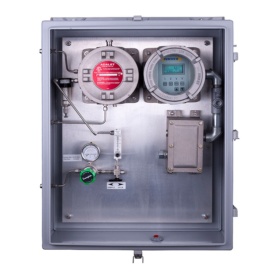
Overview The following figure illustrates an overview of the units operation. Refer to drawing number Figure 1 for details on system layout. PT605 Analyzer – Block Diagram Main Electronics and Control Assemblies Sampling System Junction Box Main CPU Board Assembly with LCD... - Page 7 Figure 1. PT605 CO2 Analyzer in fiberglass enclosure. Complete unit layout...
-
Page 8: Front Panel
Front Panel PT605 front panel is equipped with a large liquid crystal display with back light, four alarm LEDs for visual alarm indicators, and keypad switches. The CO concentration and signal output from the Infra-Red sensor are continuously displayed on the LCD. The keypad switches are used to reset alarms, calibrate sensors and program unit configuration. -
Page 9: Alarm Leds And Keypad Switches
Alarm LEDs and Keypad switches There are 4 LEDs on the front panel labeled AL1 thru AL3 and a Fault LED. These LEDs are the visual indicators of any active alarms. The alarm relays and LEDs can be reset by pressing the RESET key on the front panel. -
Page 10: Installation And Unit Startup
PT605 Analyzer is suitable for use in hazardous location. The unit can be mounted to the wall or panel. Refer to figure 2 for the mounting holes and dimensions on the fiberglass enclosure. - Page 11 Figure 2. Fiberglass Enclosure for PT605 CO2 Analyzer ...
-
Page 12: System Wiring
Simply connect the positive and negative supply lines to the connector pin labeled as + and -, respectively. 4-20mA analog output: PT605 Analyzer generates a linear 4-20mA DC analog output equivalent to CO concentration in the stream. This analog output can be connected to devices like PLC, DCS and chart recorders. - Page 13 Figure 3. User connection and Terminations for Power, alarms, and 4-20mA analog output...
-
Page 14: Alarm Relay Contacts
MODBUS Communication later in this document for additional details. Connecting the gas stream to the analyzer PT605 requires a clean and dry gas sample from the process stream for proper operation. A minimum of 50 PSIG line pressure is needed. In normal operation the pressure should not exceed 500 PSIG. -
Page 15: Unit Startup Check List
Unit Startup Check list Use the following steps as a guide for proper startup procedure. Unit must be installed in shaded area to avoid extreme heat conditions. Perform all the system wiring as discussed in the previous section. ... - Page 16 Important Installation & Maintenance Note Do not block Vents on the system enclosures. There is a vent located on the right side of the enclosure. This vent must be left open to atmosphere and must not have any back pressure. Blocking vent or attaching long tubes on these vents will create back pressure that may result in sensor contamination.
-
Page 17: Sensor Calibration
Sensor Calibration Typically the CO2 concentration of the calibration gas should be close to 50% of the full scale range of the analyzer. The following table lists the calibration gas for analyzer with different full scale range. Recommended Range of Analyzer Calibration Gas 2.5 % 10 %... - Page 18 Step by Step Calibration Procedure Remove the cap from the calibration port of the three way valve installed. Move the valve handle to CALIB position. This will shut off the sample input from the stream and allow the calibration gas to flow to the sensor. Connect the calibration gas to the CALIB port on the valve. When applying the nitrogen or calibration gas be sure the gas flow indicated in the flow meter is 1.0 SCFH.
- Page 19 STEP 4. After purge cycle the following message will be displayed. Apply Calib Gas CO2 = 0.0 SensrSignl = 0.4 v The unit is now ready for gas standard. Apply the CO2 calibration gas and make sure the flow meter is set at 1.0 SCFH. Calibration gas must be applied for at least 2 minutes. When the Sensor Signal reading has stabilized then by using ▲...
-
Page 20: Tips On Good Calibration
Tips on good calibration In order to perform good calibration, follow the instructions below Make sure the flow meter is stable and set at 1 SCFH. Not enough pressure on the calibration gas may cause flow meter to fluctuate and will result in inconsistent flow of gas through the sensor. -
Page 21: Fine Tuning Of 4-20Ma Analog Output
Fine tuning 4-20mA Analog Output All the 4-20mA analog output adjustments are performed at the factory. However, the user may desire to fine-tune the analog output. First make sure that the load is connected or the analog output terminal is connected to a PLC and then follow the instructions below. -
Page 22: Alarm Relays
Alarm Relays PT605 has three alarm relays each of which can be individually configured. The alarm set points can be anywhere between 0 and the range of the analyzer and can be latching or non- latching. Non-latching alarms are deactivated when the concentration of the CO... - Page 23 Unit Address (for MODBUS Communication) PT605 analyzer must be assigned a unique address to communicate with user PLC via MODBUS RTU protocol. The default address is 120. Refer to figure 3 for terminal assignments on the connection board for RS485 wiring connection.
-
Page 24: Modbus Rtu Communication
MODBUS RTU protocol. Only the PLC / Controller can make requests to read the contents of the data register in PT605. A unique address must be assigned to Model PT605 analyzer in order for the PLC to request data from the unit. Refer to previous section for assigning address to the analyzer. - Page 25 Modbus Registers Description 40001 Heart Beat register. Simply a counter that is increment every second to indicate the analyzer is operating properly The counter overflows to 0 after 65535 (approx 18 hours) 40002 Spare not used. Value read would be 0 40003 Current analyzer mode.
- Page 26 Modbus Registers Description 40009 Spare (not used) 40010 Calibration data: Zero Set point (integer value of volts /100) For example 90 means 0.90 volts of zero or baseline sensor signal voltage 40011 Calibration data: Span Set point (integer value of volts /100) For example 160 means 1.60 volts of net span sensor signal 40012...
-
Page 27: Replacing Analyzer Sensor Assembly
Replacing Analyzer Sensor Assembly Sensor should be replaced if the accuracy is not to the desired level even after calibration of the sensor as discussed in the previous sections. Refer to system layout drawing for the location infra red sensor assembly and the sensor connection the user termination board. -
Page 28: Care
Care PT605 should not be installed facing the direct sunlight. Installation in an extreme high temperature region should be avoided. All the covers must be tightly installed to avoid any electrical hazards and to avoid any dust or water getting inside the unit. -
Page 29: Spare Parts List
Spare Parts List Part Number Description Front Panel assembly with LCD display, where xxx determines the full scale range as follows: 005 Range 0-5 % 010 Range 0-10 % S-68-xxx 020 Range 0-20 % 050 Range 0-50 % 001 ...
Need help?
Do you have a question about the PT605 and is the answer not in the manual?
Questions and answers