Table of Contents
Advertisement
Quick Links
Advertisement
Table of Contents

Summary of Contents for PEMTECH PT750 Series W
- Page 1 Gas Detection Technology Houston, Texas Installing Wireless Annunciator to existing Fixed and Wireless Gas Detection Control Panels Rev 1 23 March 2016 www.pem-tech.com ▌ ▌ 12144 Dairy Ashford Road, Building 2, Sugar Land, Texas 77478 Ph: 281-494-2069 Fax: 281-494-2167...
- Page 2 Installing Wireless Annunciator to existing Fixed and Wireless Gas Detection Control Panels This following is the step by step procedure to convert currently “Wired” Annunciator (with touch screen) to a wireless Annunciator that monitors both the PT920 series Fixed control panel and PT2008 Wireless Controller.
- Page 3 4. Install RS485 wireless transmitter to PT2008 controller also. 5. PT2008 Repeater panel does not require any upgrade or change. It is compatible with new design. NOTE The RS485 wireless transmitter simply requires the power connection (24VDC) and the RS485 connection from the PT920 control panel or PT2008 Connection board.
- Page 5 ...
- Page 6 Gas Detection Technology Houston, Texas Wireless Annunciator for Fixed and Wireless Gas Control Panels Operators Manual Rev 1 23 March 2016 www.pem-tech.com ▌ ▌ 12144 Dairy Ashford Road, Building 2, Sugar Land, Texas 77478 Ph: 281-494-2069 Fax: 281-494-2167...
-
Page 7: System Overview
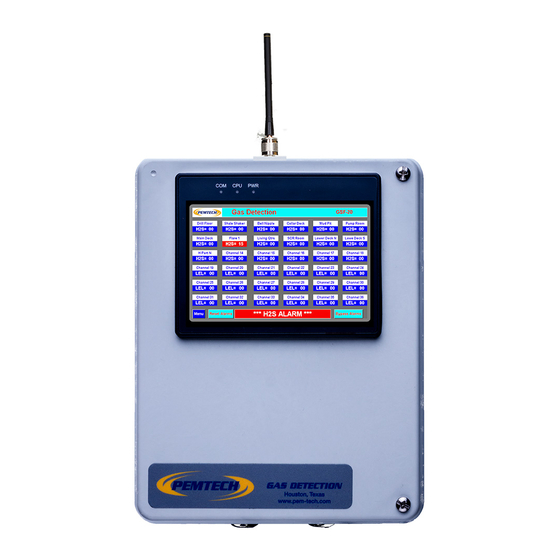
System Overview Model PT750 Series Wireless Annunciator is designed to communicate with the Fixed Gas Control panel on the main Rig and the Wireless Control Panel on the Rig Camp. The line of sight distance is 2 Km using dipole antenna. The color touch screen display provides continuous gas readings for all the detectors connected to the (fixed) main control panel and the wireless controller. - Page 8 Startup Upon unit power up a system information screen is displayed for few seconds and then normal data screen is displayed. Figure 1 System Startup Information Screen Figure 2 Normal Data Display Screen The normal mode the unit display data from all the gas detectors interface to fixed and wireless controller.
-
Page 9: System Configuration
System Configuration The only configuration required is to assign sensor location tags for the controllers and then select if channel is enabled or disabled. To configure press the MENU button on the lower left corner of the display screen and the following screen is displayed. Figure 3 System Configuration Screen To select the option simply press the button or touch the edit field and a keypad will appear on the screen. - Page 10 Sensor Enable or Disable The channel must be properly enabled or disabled. On the Fixed control panel if the module / detector is not installed then that channel is simply disabled. Similarly on the Wireless control panel if any channel is not active then the same channel must be disabled on the annunciator.
- Page 11 Figure 5 Sensor Location Tags and Enable/Disable for Wireless Gas Controller...
-
Page 12: Alarm Test
Alarm Test This feature is used as a functional test for alarms. In many application this feature is also used as a drill to check the readiness of the personnel on location to take necessary precautionary actions. On the System configuration menu screen press the “Alarm Test” button and the following screen will be displayed. -
Page 13: Normal Operation
Normal Operation In normal operation the display screen will show the live reading of all the detectors. The data on the screen is typically updated every 2 to 3 seconds. Each data block for a sensor displays the gas readings as well as any diagnostic and trouble message. Following are sample data display for a sensor. -
Page 14: Alarm Condition
Alarm Condition If the sensor goes into alarm the sensor data reading starts flashing in red. Also the bold alarm messages starts flashing on the status bar at the bottom of the screen. Once the alarm clears the red flashing messages are cleared. However, the sensor location tag will still be flashing. -
Page 15: Alarm Reset
Alarm Reset When RESET button is pressed, the annunciator will send command to the control panels to deactivate the alarms. However, if the high gas condition still exists the control panel will reactivate the alarms. If alarms are cleared, pressing the RESET will clear the flashing sensor location tags if any. - Page 17 ...
Need help?
Do you have a question about the PT750 Series W and is the answer not in the manual?
Questions and answers