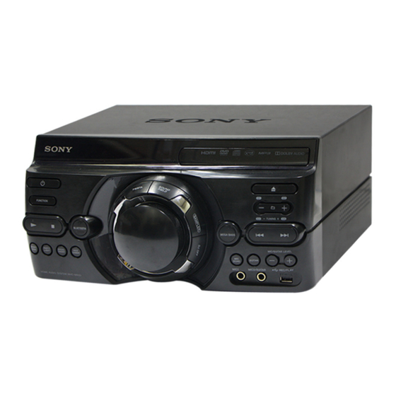
Sony HCD-M40D Service Manual

Sony HCD-M40D Service Manual

Cd/dvd receiver

Advertisement

SERVICE MANUAL
Ver. 1.0 2018.02
• HCD-M40D is the tuner, USB, DVD Player, Bluetooth and amplifi er section in MHC-M40D.
• HCD-M60D is the tuner, USB, DVD Player, Bluetooth and amplifi er section in MHC-M60D.
• HCD-M80D is the tuner, USB, DVD Player, Bluetooth and amplifi er section in MHC-M80D.
Note:
Be sure to keep your PC used for service and
checking of this unit always updated with the
latest version of your anti-virus software.
In case a virus aff ected unit was found during
service, contact your Service Headquarters.
Inputs
AUDIO IN (TV) L/R:
Voltage 2 V, impedance
47 kilohms
TV (ARC):
Supported audio signal:
2-channel Linear PCM
MIC1:
Sensitivity 1 mV, impedance
10 kilohms
MIC2/GUITAR:
Sensitivity 1 mV, impedance
10 kilohms (When guitar mode is turned
off.)
Sensitivity 200 mV, impedance
250 kilohms (When guitar mode is
turned on.)
Outputs
HDMI OUT (TV) ARC:
Supported audio signal:
2-channel Linear PCM (up to
48 kHz), Dolby Digital
HDMI section
Connector:
Type A (19 pin)
Disc player section
System:
Compact disc and digital audio and
video system
9-890-693-01
Sony Corporation
2018B80-1
©
2018.02
Published by Sony EMCS (Malaysia) PG Tec
Photo: HCD-M80D
Model Name Using Similar Mechanism
DVD Section
DVD Mechanism Type
Optical Pick-up Name
SPECIFICATIONS
Laser Diode Properties
Emission Duration: Continuous
Laser Output*: Less than 44.6 μW
* This output is the value measurement
at a distance of 200 mm from the
objective lens surface on the Optical
Pick-up Block with 7 mm aperture.
Frequency response:
20 Hz – 20 kHz
Video color system format:
Latin American model:
NTSC
Other models:
NTSC and PAL
USB section
Supported USB device:
Mass Storage Class
Maximum current:
1 A
(USB) port:
Type A
FM tuner section
FM stereo, FM superheterodyne tuner
Antenna:
FM lead antenna
Tuning range:
76 MHz - 108 MHz (100 kHz step)
(Brazilian model)
87.5 MHz – 108.0 MHz (50 kHz step)
(except Brazilian model)
HCD-M40D/M60D/
MHC-V50/V50D
CDM90-DVBU204//C
CMS-S76RFS7GP OR CMS-S76RFS7G1
BLUETOOTH section
Communication system:
BLUETOOTH Standard version 4.2
Output:
BLUETOOTH Standard Power Class 2
Maximum output power:
< 9.5 dBm
Maximum communication range:
Line of sight approx. 10 m
*1
Maximum number of devices to be registered
8 devices
Maximum number of simultaneous connection
(Multipoint)
3 devices
Frequency band:
2.4 GHz band (2.4000 GHz –
2.4835 GHz)
Modulation method:
FHSS (Freq Hopping Spread Spectrum)
Compatible BLUETOOTH profiles
*2
:
A2DP (Advanced Audio Distribution
Profile)
AVRCP (Audio Video Remote Control
Profile)
SPP (Serial Port Profile)
Supported codecs:
SBC (Subband Codec)
AAC (Advanced Audio Coding)
LDAC
CD/DVD RECEIVER
M80D
AEP Model
HCD-M60D
Russian Model
E Model
Australian Model
HCD-M40D/M60D/M80D
Brazilian Model
HCD-M60D/M80D
*1
The actual range will vary depending on
factors such as obstacles between devices,
magnetic fields around a microwave oven,
static electricity, reception sensitivity,
antenna's performance, operating system,
software application, etc.
*2
BLUETOOTH standard profiles indicate the
purpose of BLUETOOTH communication
between devices.
Supported audio formats
Supported bit rate and sampling frequencies:
MP3:
32/44.1/48 kHz, 32 kbps – 320 kbps
(VBR)
AAC:
44.1 kHz, 48 kbps – 320 kbps
(CBR/VBR)
WMA:
44.1 kHz, 48 kbps – 192 kbps
(CBR/VBR)
WAV:
44.1/48 kHz (16 bit)
– Continued on next page –

Advertisement

Table of Contents
loading

Summary of Contents for Sony HCD-M40D

  • Page 1 HCD-M60D/M80D Photo: HCD-M80D • HCD-M40D is the tuner, USB, DVD Player, Bluetooth and amplifi er section in MHC-M40D. • HCD-M60D is the tuner, USB, DVD Player, Bluetooth and amplifi er section in MHC-M60D. • HCD-M80D is the tuner, USB, DVD Player, Bluetooth and amplifi er section in MHC-M80D.
  • Page 2 FOR HDMI] is set to [ON].) trademarks owned by the Bluetooth SIG, Inc. and any use of such Dimensions (w/h/d) (excl. speakers) marks by Sony Corporation is under license. Other trademarks and (Approx.): trade names are those of their respective owners.
  • Page 3 HCD-M40D/M60D/M80D NOTES ON CHIP COMPONENT REPLACEMENT • Never reuse a disconnected chip component. • Notice that the minus side of a tantalum capacitor may be damaged by heat. FLEXIBLE CIRCUIT BOARD REPAIRING • Keep the temperature of the soldering iron around 270 °C during repairing.
  • Page 4: Table Of Contents

    HCD-M40D/M60D/M80D TABLE OF CONTENTS SERVICING NOTES 6-13. Printed Wiring Board - SMPS Board (M40D) - ..... 48 ..........6-14. Printed Wiring Board - SMPS Board (M60D/M80D) - ........49 DISASSEMBLY 6-15. Printed Wiring Board - PANEL Board - ......50 2-1.
  • Page 5: Servicing Notes

    During repair, pay attention to electrostatic break-down and also use the procedure in the printed matter which is included in the HCD-M60D: RU 4-732-800-7[] repair parts. HCD-M40D: LA9 4-732-801-0[] The fl exible board is easily damaged and should be handled with HCD-M40D: AUS 4-732-801-3[] care.
  • Page 6 Music: J-6090-071-A DISC (HLX-501), TEST (NTSC) MP3 fi les (.mp3) *1*2 J-6090-089-A DISC (HLX-505), TEST (NTSC) • Video (HCD-M40D/M60D/M80D): J-2501-306-A DISC (HLX-514), TEST (NTSC) MPEG4 fi les (.mp4/.m4v) , Xvid fi les (.avi) *2*3 J-6090-078-A DISC (HLX-507), TEST (PAL) PLAYABLE FILES ON USB DEVICE If “PROTECTX”...
  • Page 7 HCD-M40D/M60D/M80D NOTE OF REPLACING THE IC3501 (M80D), IC3502, – MOTHERBOARD Board (M40D) (Component Side) – IC3503 (M60D, M80D) AND IC2002 ON THE MOTH- ERBOARD BOARD AND THE COMPLETE MOTHER- BOARD BOARD When IC3501 (M80D), IC3502, IC3503 (M60D, M80D) and thermal compound (TIG2000)
  • Page 8 HCD-M40D/M60D/M80D HOW TO OPEN THE TRAY WHEN POWER SWITCH TURN OFF Note 1: After the cover, top is removed, this work is done. Note 2: Please prepare the thin wire (clip etc. processed to the length of 8 cm or more).
  • Page 9 C7217 800 /5 W C7701 800 /5 W C7606 SMPS Board (Conductor side view) (HCD-M40D) In checking the SMPS board, make 3 capacitors discharge of C6301, C6302 and C6503 for eletrical shock prevention. 800 /5 W C6503 800 /5 W...
  • Page 10 HCD-M40D/M60D/M80D SERVICE POSITION HCD-M40D sheet VFD_IR board MOTHERBOARD board PANEL board Fan, DC SMPS board HCD-M60D LED CONNECTOR board sheet VFD_IR board MOTHERBOARD board PANEL board SMPS board DC fan HCD-M80D MOTHERBOARD board sheet VFD_IR board LED DRIVER board PANEL board...
  • Page 11: Disassembly

    HCD-M40D/M60D/M80D SECTION 2 DISASSEMBLY Note: Disassemble the unit in the order as shown below. 2-1. DISASSEMBLY FLOW 2-2. TOP COVER (Page 12) 2-3. LOADING PANEL SECTION (Page 12) 2-4. CDM SECTION (M40D) 2-5. CDM SECTION (M60D/M80D) (Page 13) (Page 14) 2-6.
  • Page 12: Top Cover

    HCD-M40D/M60D/M80D Note: Follow the disassembly procedure in the numerical order given. 2-2. TOP COVER 4 cover, top 1 six screws (+BVTP 3 2-3. LOADING PANEL SECTION 3 three claws 1 Insert the clip etc. 4 panel, loading hole section – Side view –...
  • Page 13: Cdm Section (M40D)

    HCD-M40D/M60D/M80D 2-4. CDM SECTION (M40D) 4 one screw (+BVTP 3 7 CDM section 3 flexible flat cable (24 core) (CN302) 5 one screw, tapping 2 flexible flat cable (5 core) (CN303) 1 CN402 (4P) Note 2: When you install the connector, please install them correctly.
  • Page 14: Cdm Section (M60D/M80D)

    HCD-M40D/M60D/M80D 2-5. CDM SECTION (M60D/M80D) one screw 9 CDM section (+BVTP 3 (M80D) filament tape hook (sub material) CDM90-DVBU204//C 5 flexible flat cable (24 core) (CN302) 4 flexible flat cable (5 core) (CN303) CN402 (4P) (M60D) hook MOTHERBOARD board screw, tapping...
  • Page 15: Cdm90-Dvbu204//C

    HCD-M40D/M60D/M80D 2-6. CDM90-DVBU204//C 3 four screws (BVTP 3 6 CDM90-DVBU204//C 4 Draw three wires out of the hole in bracket CDM section. 1 one screw (BVTP 3 2 bracket, support 5 holder, CDM – CDM section front view –...
  • Page 16: Service, Optical Device (7G), Flexible Flat Cable

    HCD-M40D/M60D/M80D 2-7. SERVICE, OPTICAL DEVICE (7G), FLEXIBLE FLAT CABLE 1 six claws 2 chuck holder assy (MB) ql flexible flat cable (24 core) qg flexible flat cable (5 core) qf filament tape qa insulator filament tape (sub material) (sub material)
  • Page 17: Front (H/M/L) Panel Section

    HCD-M40D/M60D/M80D 2-8. FRONT (H/M/L) PANEL SECTION (M40D) (M60D) 3 claw 3 claw 3 claw 3 claw (M80D) 1 flexible flat cable (17 core) (CN122) (M60D/M80D) 3 claw flexible flat cable (15 core) (CN102) (M40D) 2 one screw (+BVTP 3 3 claw...
  • Page 18: Motherboard Board, Fan Dc (M40D)

    HCD-M40D/M60D/M80D 2-9. MOTHERBOARD BOARD, FAN DC (M40D) two screws (+PWH 3 8 (SUMITITE)) wa fan, DC qg heat sink (MB-L) Note 1: When you install the heat sink (MB-L), spread the compound referring to “NOTE OF REPLACING THE IC3501 (M80D), IC3502, w;...
  • Page 19: Motherboard Board, Dc Fan (M60D)

    HCD-M40D/M60D/M80D 2-10. MOTHERBOARD BOARD, DC FAN (M60D) qk heat sink (MB-M) Note 1: When you install the heat sink (MB-M), spread the compound referring to “NOTE OF REPLACING THE IC3501 (M80D), IC3502, IC3503 (M60D, M80D) AND IC2002 ON THE MOTHERBOARD BOARD AND THE COMPLETE MOTHERBOARD BOARD”...
  • Page 20: Motherboard Board, Dc Fan (M80D)

    HCD-M40D/M60D/M80D 2-11. MOTHERBOARD BOARD, DC FAN (M80D) qk heat sink (MB-H) Note 1: When you install the heat sink (MB-H), spread the compound referring to “NOTE OF REPLACING THE IC3501 (M80D), IC3502, IC3503 (M60D, M80D) AND IC2002 ON THE MOTHERBOARD BOARD AND THE COMPLETE MOTHERBOARD BOARD”...
  • Page 21: Smps Board, Mic Usb Board (M40D)

    HCD-M40D/M60D/M80D 2-12. SMPS BOARD, MIC USB BOARD (M40D) 1 two screws (+PWH 3 8 (SUMITITE)) 1 four screws (+PWH 3 8 (SUMITITE)) 2 SMPS board 3 two screws (+BVTP 3 4 MIC USB board chassis, bottom section...
  • Page 22: Smps Board, Mic Usb Board (M60D/M80D), Dc Fan (M80D)

    HCD-M40D/M60D/M80D 2-13. SMPS BOARD, MIC USB BOARD (M60D/M80D), DC FAN (M80D) 2 four screws (+BVTP 3 1 Remove the cable from the hook 3 chassis, sub hook 4 five screws (+PWH 3 8 (SUMITITE)) chassis, sub (M80D) 4 four screws...
  • Page 23: Test Mode

    3. “COLD RST” appears on the screen display panel. After that, 4. Press [  - ] button, the button and knob check mode is “SONY” appears on the screen display panel. The system au- activated. tomatically turn on and off once. Please be sure that the system 5.
  • Page 24: Electrical Check

    HCD-M40D/M60D/M80D SECTION 4 ELECTRICAL CHECK FOCUS BIAS CHECK TUNER SECTION 0 dB = 1 V oscilloscope FM AUTO STOP CHECK (DC range) signal MOTHERBOARD board generator CN302 pin 17 (RF) CN302 pin 1 (GND) – Procedure: 1. Connect the oscilloscope to CN302 pin 17 (RF) and CN302 pin 1 (GND) on the MOTHERBOARD board.
  • Page 25: Troubleshooting

    HCD-M40D/M60D/M80D SECTION 5 TROUBLESHOOTING...
  • Page 26 HCD-M40D/M60D/M80D...
  • Page 27 HCD-M40D/M60D/M80D...
  • Page 28 HCD-M40D/M60D/M80D...
  • Page 29 HCD-M40D/M60D/M80D...
  • Page 30 HCD-M40D/M60D/M80D...
  • Page 31 HCD-M40D/M60D/M80D...
  • Page 32 HCD-M40D/M60D/M80D...

This manual is also suitable for:

Hcd-m60dHcd-m80d

Table of Contents