Table of Contents
Advertisement
Quick Links
TJERNLUND PRODUCTS, INC.
1601 Ninth Street • White Bear Lake, MN 55110-6794
PHONE (800) 255-4208 • (651) 426-2993 • FAX (651) 426-9547
Visit our web site • www.tjernlund.com
INSTALLATION INSTRUCTIONS
Recognize this symbol as an indication of important Safety Information!
!
OWNER INSTRUCTIONS, DO NOT DESTROY
WARNING
!
THESE INSTRUCTIONS ARE INTENDED AS AN AID TO QUALIFIED, LICENSED
SERVICE PERSONNEL FOR PROPER INSTALLATION, ADJUSTMENT AND
OPERATION OF THIS PRODUCT. READ THESE INSTRUCTIONS THOROUGHLY
BEFORE ATTEMPTING INSTALLATION OR OPERATION. FAILURE TO FOLLOW
THESE INSTRUCTIONS MAY RESULT IN IMPROPER INSTALLATION, ADJUST-
MENT, SERVICE OR MAINTENANCE POSSIBLY RESULTING IN FIRE, ELECTRI-
CAL SHOCK, CARBON MONOXIDE POISONING, EXPLOSION, PERSONAL
INJURY OR PROPERTY DAMAGE.
DO NOT DESTROY. PLEASE READ CAREFULLY AND
KEEP IN A SAFE PLACE FOR FUTURE REFERENCE.
Copyright © 2014, Tjernlund Products, Inc. All rights reserved
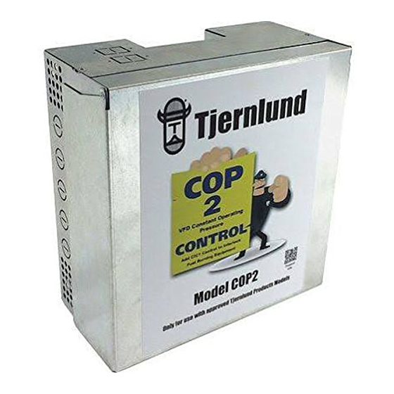
MODEL COP2
(Includes COP2 Control and Transducer)
P/N 8504208
Advertisement
Table of Contents

Summary of Contents for TJERNLUND COP2
- Page 1 MENT, SERVICE OR MAINTENANCE POSSIBLY RESULTING IN FIRE, ELECTRI- CAL SHOCK, CARBON MONOXIDE POISONING, EXPLOSION, PERSONAL INJURY OR PROPERTY DAMAGE. DO NOT DESTROY. PLEASE READ CAREFULLY AND KEEP IN A SAFE PLACE FOR FUTURE REFERENCE. Copyright © 2014, Tjernlund Products, Inc. All rights reserved P/N 8504208...
-
Page 2: Table Of Contents
CIC1 Interlock Control and perform operation check to validate the interface with the COP2 Control. 2. The COP2 is intended for indoor installation only. Do not mount the COP2 on a heat source or in an environment that exceeds 104 o F (40 o C). -
Page 3: Sizing A Common Manifold Serving Multiple Dryers
Using the key hole slots on the back of the COP2 junction box as a template, mark (4) holes on the mounting surface, drill 1/4” pilot holes for wall anchors if necessary, and secure junction box using provided screws. -
Page 4: Sensing Sampling Tube Location & Installation
COP2 Control. If mounting on the side of the duct is unavoidable, the sensing tube should be flush to the interior wall of the duct. -
Page 5: Wiring Connections Between Cop2 And Rt-Series Rooftop Fan
C22.1-12 Canadian Electrical Code in Canada. All wiring from the COP2 to the RT-Series Fan junction box must be appropriate Class 1 wiring as follows: installed in rigid metal conduit, intermediate metal conduit, rigid non-metallic conduit, electrical metallic tubing, Type MI Cable, Type MC Cable, or be otherwise suitably protected from physical damage. - Page 6 RT-SERIES FAN CONNECTIONS TO COP2 CONTROL Secure the junction box on the opposite end of COP2 whip to the power supply conduit. Wire nut the 5 leads from the COP2 (Red, White/Red, Ground, Black and White) to the corresponding colors of the RT Series Whip. Stuff Wires into 4 x 4 box on whip.
- Page 7 COP2 SYSTEM WIRING LEGEND = LOW VOLTAGE WARNING = 115 VAC Do not use the COP2 with gas or oil fired heating EXHAUSTER equipment without interlocking all burners being COOLING FAN served with a CIC1 Interlock Control and the IF APPLICABLE...
-
Page 8: Adjusting The Pressure (Exhaust) Set Point & Balancing Individual Connections
The pressure set point is adjusted by positioning dip switches 6 - 1 to match the desired setting listed on the Pressure Setpoint Table below. The factory set point is 0.10” W.C. The dip switches are located on the Red block on the top of the COP2 circuit board. -
Page 9: Adjustment Of Balancing Baffle(S) For Kitchen And Bath Fans
Top LED is Green Verify that the supply power to the COP2 is switched on and the Activation terminals C1 & C2 are closed with a switch or jumper to start the RT-Series fan. Disconnect the sensing tube from the barbed fitting on the Transducer electrical box. The fan should ramp to full speed. - Page 10 If voltage to and from the Transducer are in the ranges listed above, measure COP2 VFD output AC voltage at the Red and WHT/RED stripe terminals with the Transducer tube still disconnected. Look for a reading of around 125 volts AC.
- Page 11 TJERNLUND LIMITED ONE YEAR WARRANTY Tjernlund Products, Inc. warrants to the original purchaser of this product that the product will be free from defects due to faulty material or work- manship for a period of (1) year from the date of original purchase or delivery to the original purchaser, whichever is earlier. Remedies under this warranty are limited to repairing or replacing, at our option, any product which shall, within the above stated warranty period, be returned to Tjernlund Products, Inc.


Need help?
Do you have a question about the COP2 and is the answer not in the manual?
Questions and answers