Table of Contents
Advertisement
Quick Links
Advertisement
Table of Contents

Related Manuals for Concept2 SENTINEL S55 v6

Summary of Contents for Concept2 SENTINEL S55 v6
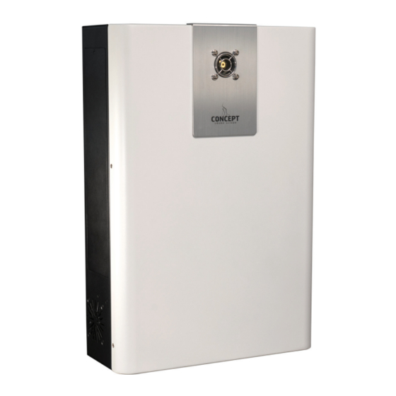
- Page 1 SENTINEL S55 v6 INSTALLATION AND OPERATION MANUAL Version: November 2020...
- Page 2 Thank you for purchasing a Concept Smoke Screen system. Your choice to protect your property and premises with this equipment has given you the use of one of the most effective security systems currently available. Concept Smoke Screen systems have been in service for over 35 years and have protected many millions of pounds worth of property, defeating criminals and securing premises on an almost daily basis.
-
Page 3: Table Of Contents
CONTENTS General Safety instructions………………………………………………………………………………………..…………………….………..........How does your Smoke Screen work?………………………………….…………………………………...……………..........Introduction……………..…………………………………………………………………………………………………………………..........Overview……………………………………………………...……………………………………………………………………………..........Typical installations……………….…………………………………………………………………………………………………..........Location Positioning……………………………….…………………….………………………………..…………………………………………..........Installation procedure.………………………………………………………………………….……………………………………..........Servicing access.……………………………….……………………………………..………………………………………………..........Mounting…………..……….……………………….………………………………………...……………………………………………..........Nozzle changing…………………………………………………………………..……………………………………………………..........Function Controlling the smoke……………………………………..………………………………………………………………………..........Outputs………………………………………………………………………………………………………………..……………….……..........Connections Circuit board layout……………………………………………………………………………………………………………………..........Generic connection diagram……………………….…………………………….…….………………………………………..........Settings Screen sensor……………….………..……………………………………………..……….…………………………………………..........Energy saving mode……………………………………………………….………...………..……………………………………..........Verification timer………………………………………………………………………………………………………………………........... -
Page 4: General
General 1.1 SAFETY INSTRUCTIONS Before installing and using the Smoke Screen read, follow and retain this manual and safety instructions for future reference. To reduce the risk of severe injury or death to persons, or damage to the Smoke Screen: Do not work on the Smoke Screen unless qualified by the manufacturer to do so. -
Page 5: Introduction
1.3 INTRODUCTION This manual covers the Sentinel S55. Before commencing installation of the Smoke Screen ensure that you have all the following equipment supplied in the box: 1 x Smoke Screen. • 1 x Mounting bracket. • Swift-Fit fluid reservoir (boxed). -
Page 6: Typical Installations
1.5 TYPICAL INSTALLATIONS A typical installation can be configured in the following way: The Smoke Screen is wall or ceiling mounted in the appropriate location. • A Hold-off PIR (or similar device) located within the same area as the Smoke Screen providing a •... -
Page 7: Location
Location 2.1 POSITIONING The Smoke Screen should ideally be sited in a covert position away from prying eyes and thereby reducing the possibility of tamper or an attack. The ideal place for the Smoke Screen is above a ceiling from where the smoke plume is used to its best effect, bursting on the ground and spreading outwards and upwards through 360°. -
Page 8: Installation Procedure
2.2 INSTALLATION PROCEDURE Site the Smoke Screen and fix to the wall or ceiling as appropriate. 2. Select the “Service Mode” dip switch to “On”. Make connections as required to the alarm panel, hold-off PIR and, if used, the Panic input. Make connection to the Smoke Screen Interface (if used) and set the key switch to isolate. - Page 9 Suspension mounting Suspending the Smoke Screen is achieved using a ‘Suspension Kit’ comprising a length of unistrut, two sections of threaded bar and fixings. Suspension Kit Contents (all M8) Unistrut 1 x 1 metre Threaded bar 2 x 1 metre Fixings: 1 x ceiling hole surround 2 x drop-in anchors...
-
Page 10: Nozzle Changing
2.5 NOZZLE CHANGING To change the nozzle, first remove the front cover then remove and replace the nozzle using a 10mm ring spanner, sealing it with PTFE tape and ensuring that an angled nozzle is seated in the correct orientation. The Smoke Screen is delivered with a single-hole straight nozzle plus an extra 1-hole 30 deg angle down nozzle. -
Page 11: Function
Function 3.1 CONTROLLING THE SMOKE Alarm Panel activation There are 3 sets of input connections on the Smoke Screen (Set, Alarm and Hold-off) that should be connected to clean contacts. For the Smoke Screen to produce ‘smoke’ all 3 sets of connections must be ‘open circuit’ (this can be changed to ‘closed = activate’... -
Page 12: Outputs
Hold-off settling time A “Settle Timer” can be programmed for a period between 0 and 60 seconds (in 1 second intervals) during which the Smoke Screen will not react to a hold-off input after receiving a ‘Set’ command. Delaying an activation After the Smoke Screen has received the required 3 inputs to produce smoke, an activation can be delayed for a period between 0 and 60 seconds (in 1 second intervals). -
Page 13: Connections
Connections 4.1 CIRCUIT BOARD LAYOUT... -
Page 14: Generic Connection Diagram
4.2 GENERIC CONNECTION DIAGRAM... -
Page 15: Settings
Settings 5.1 SCREEN SENSOR A Concept Smoke Screen “Screen Sensor” can be connected to the Sentinel. When this is integrated the system detects a drop in the fog density in the protected area and will re-trigger the Sentinel to maintain the fog level. When fitted the Screen Sensor is connected to the Hold Off input pins and, consequently, it prevents the use of a hold-off detector. -
Page 16: Service Mode
5.4 SERVICE MODE Setting dip switch No 4 (see diagram under “Circuit Board Layout”) to “On” puts the Smoke Screen into “Service Mode”. This setting prevents the Smoke Screen from making smoke whilst work is conducted with power applied. To highlight that the Smoke Screen is in “Service Mode” the Tamper output is put into an alarm state. FAILURE TO DISABLE SERVICE MODE WHEN NO LONGER REQUIRED WILL PREVENT THE SMOKE SCREEN OPERATING. -
Page 17: Fluid Management
5.8 FLUID MANAGEMENT The Smoke Screen has a replaceable 1 litre Swift-Fit fluid reservoir (also known as product code SFL-1000) that is accessed by removing the cover on the right-hand side of the unit. The fluid level is monitored using sensors in the fluid reservoir to give a “Low Fluid”... -
Page 18: Battery Management
External reservoir A 5000ml external reservoir can be used with Smoke Screen, please contact Concept Smoke Screen if you wish to use this function. 5.9 BATTERY MANAGEMENT Operation The Smoke Screen is fitted with a battery to provide power to the electronic circuits and pump (not to the fluid heater) in the event of a mains power failure. -
Page 19: Programming
5.10 PROGRAMMING LCD illumination Pressing any button illuminates the LCD back-light; it automatically extinguishes after 1 minute of inactivity. Setting the time and date In the Smoke Screen Status or Current Time display: • Press and hold Function/Escape for 3 seconds until the date and time are shown with the Day flashing. •... - Page 20 Parameter settings MENU ITEM DELIVERY AVAILABLE SETTINGS REMARKS SETTING Event Log Read-only. See Section 7.2 for a list of the major events Setting Smoke Time 5 seconds 5 to 360 seconds in 1 See Section 3.1. second intervals. Setting Panic Smoke Time 0 seconds 5 to 360 seconds in 1 See Section 3.1.
-
Page 21: Commissioning
Commissioning 6.1 OPERATION While the Smoke Screen is heating up the LCD display will show a “Live Status” in code format and the LED indicator will be Yellow. If the cover is open “Tamper Fault (Ti)” will be displayed on the LCD and the LED indicator will flash yellow once every 5 seconds;... -
Page 22: Servicing
Servicing LCD LIVE STATUS INDICATIONS The Smoke Screen provides ‘Live Status’ indications on the LCD to give a quick overview of the current condition of the machine. The indications have the following meanings: Top Line (Outputs): Indication Meaning Explanation The Smoke Screen heater block is not at operating temperature and it is not ready to activate Temp Status or there is a Heater fault. -
Page 23: Lcd, Led And Sound Indications
LCD, LED AND SOUND INDICATIONS The Smoke Screen provides on-board status monitoring via an LCD, a multicolour LED and a sounder. Indications displayed are:... -
Page 24: Thermal Cut-Out (Tco) Reset
7.3 THERMAL CUT-OUT (TCO) RESET This operation is usually carried out during installation. If the Smoke Be aware of high voltage in the Screen has been in block area. The electrical supply service, the nozzles will should be switched off before be extremely hot and working in the heater block will cause injury if touched. -
Page 25: Action After Every Activation
7.4 ACTION AFTER EVERY ACTIVATION Wait until the smoke production has ceased . Do not try to enter the affected area as you will not be • able to see through the fog. Look for signs of forced entry. If you find any, or you believe that intruders are on the premises, call the •... -
Page 26: Miscellaneous
Miscellaneous 8.1 GLOSSARY Item Meaning Explanation Alarm Smoke Screen alert input Signal from Alarm panel or SSI to Smoke Screen Activation Smoke Screen making fog Dip switch PCB mounted on/off switch Drop-in anchor M8 fixing for blind holes in masonry A slight reduction in running temperature when “Unset”... -
Page 27: Faq
8.2 FAQ The Smoke Screen is indicating it is ready to operate but does not respond to a full alarm test. Ensure “Service Mode” is disabled. With power applied, and keeping clear of the smoke nozzle, disconnect the “Alarm” / ”Trigger” and “Hold-off”... - Page 28 (f) copies of any service records. CSS reserves the right to refuse warranty service if this information is not complete. CSS may repair or replace CSS products with new or reconditioned parts or products of equivalent to new performance and reliability. CSS may also replace products with equivalent models where the original has been discontinued.
- Page 29 Other information When returning the product for warranty service, please pack it very carefully and enclose the instructions for repair. CSS shall not be liable for any incidental or consequential damages for breach of any express or implied warranty of this product. These warranty terms and conditions are offered to you by CSS without prejudice to any statutory rights that you may additionally have with regard to the products covered by these terms and conditions.
-
Page 30: Installer Notes
8.5 INSTALLER NOTES... - Page 31 SENTINEL S55 v6 (Version November 2020) Concept Smoke Screen Limited North End Business Park, Station Rd, Swineshead, Lincolnshire, PE20 3PW United Kingdom Tel: +44 (0) 1205 821111 | Fax : +44 (0) 1205 820316 | info@smoke-screen.co.uk | www.smoke-screen.com...
Need help?
Do you have a question about the SENTINEL S55 v6 and is the answer not in the manual?
Questions and answers