Advertisement
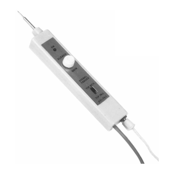
Signal Tracer Kit
MODEL ST-751
Assembly Instructions
®
Elenco
Electronics, Inc.
Copyright © 2005, 1996 by Elenco
®
Electronics, Inc. All rights reserved.
753031
Revised 2005
REV-E
No part of this book shall be reproduced by any means; electronic, photocopying, or otherwise without written permission
from the publisher.
Advertisement
Table of Contents

Related Manuals for Elenco Electronics ST-751


Summary of Contents for Elenco Electronics ST-751
- Page 1 Signal Tracer Kit MODEL ST-751 Assembly Instructions ® Elenco Electronics, Inc. Copyright © 2005, 1996 by Elenco ® Electronics, Inc. All rights reserved. 753031 Revised 2005 REV-E No part of this book shall be reproduced by any means; electronic, photocopying, or otherwise without written permission...
-
Page 2: Parts List
Parts List If you are a student, and any parts are missing or damaged, please see instructor or bookstore. If you purchased this signal tracer kit from a distributor, catalog, etc., please contact Elenco Electronics (address/phone/e-mail is at the back of this manual) for ®... -
Page 3: Parts Verification
Introduction Assembly of your signal tracer will prove to be an exciting project and give much satisfaction and personal achievement. If you have experience in soldering and wiring techniques, you should have no problems. For the beginner, care must be given to identifying the proper components and good soldering habits. - Page 4 Step-by-Step Assembly Instructions Refer to Figure 1, install and solder the following resistors. 100kW 5% 1/4W 100kW 5% 1/4W 10kW 5% 1/4W 180kW 5% 1/4W 6.8kW 5% 1/4W 100W 5% 1/4W 220kW 5% 1/4W 4.7kW 5% 1/4W 10kW 5% 1/4W 1kW 5% 1/4W 47kW 5% 1/4W 2.7kW 5% 1/4W...
- Page 5 Refer to Figure 1 or the top legend on the PC board. Install and solder the following capacitors. .001mF (102) Discap .1mF (104) Discap .1mF (104) Discap 10mF Lytic (see Figure 4) 10mF Lytic (see Figure 4) 10mF Lytic (see Figure 4) .1mF (104) Discap 10mF Lytic (see Figure 4) Install and solder the transistors with the flat side in the direction shown...
- Page 6 Prepare the power cord. On one end, use diagonal cutters to strip off 4” of the gray casing to expose 3 wires (BE CAREFUL NOT TO CUT INTO THE 3 WIRES). Strip off 2” of gray casing off of the other end. Strip 1/4”...
- Page 7 Jack Cable Notch Jack Notch Install the label onto the case. Be careful to place the label on neatly and correctly. Peel the backing off the expose the glue. Place the PC board assembly into the case as shown in Figure 6. Use two #4 screws to hold the case together.
- Page 8 Testing the Signal Tracer Checking out your signal tracer is fairly easy. You will need a DC voltage source of between 5 to 40V. A 9V battery will do fine. Connect the red alligator clip lead to the positive voltage and the black lead to the negative voltage.
-
Page 9: Theory Of Operation
Theory of Operation The diagram on the back cover shows the schematic diagram of the signal tracer. Its main component is the dual op-amp LM-358. The first section serves as a squarewave oscillator. Positive feedback is through resistor R3. The frequency of oscillation is controlled by resistor R4 and capacitor C1. -
Page 10: Troubleshooting Guide
Troubleshooting Guide The following guide should help in solving any problems encountered with your signal tracer. First, check your unit for soldering or wiring errors. Next, check the voltage at the emitter of transistor Q1. It should measure between 4.5 to 5.5 volts. If you still have a problem, refer to the following sections for help. -
Page 11: Customer Service
Specifications Injector: Pick Up: DC Input Voltage: 5 to 40 volts Input Current: Customer Service In the event that you encounter difficulty in getting the instrument to work properly, write or e-mail (elenco@elenco.com) us and explain: (1) the tests that you have made and (2) how the instrument behaved during these tests. -
Page 12: Schematic Diagram
Schematic Diagram Elenco Electronics, Inc. ® 150 Carpenter Avenue Wheeling, IL 60090 (847) 541-3800 Website: www.elenco.com e-mail: elenco@elenco.com...
Need help?
Do you have a question about the ST-751 and is the answer not in the manual?
Questions and answers