Advertisement
Quick Links
SERVICE AND PARTS MANUAL FOR
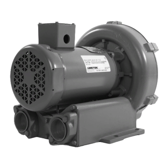
BLOWER MODEL
CP101 – CP404
AMETEK Dynamic Fluid Solutions
100 East Erie St., Kent, Ohio 44240
Telephone: 330-673-3452 Fax: 330-677-3306
email: dfs.information@ametek.com
internet: www.ametekdfs.com
Your Choice. Our Commitment.™ ™ ™ ™
Advertisement

Summary of Contents for Ametek CP101
- Page 1 SERVICE AND PARTS MANUAL FOR BLOWER MODEL CP101 – CP404 AMETEK Dynamic Fluid Solutions 100 East Erie St., Kent, Ohio 44240 Telephone: 330-673-3452 Fax: 330-677-3306 email: dfs.information@ametek.com internet: www.ametekdfs.com Your Choice. Our Commitment.™ ™ ™ ™...
- Page 2 Subsequent customer failures due to abuse, misuse, misapplication or repeat offense will not be covered. AMETEK Rotron will then notify you of your options. Any failed unit that is tampered with by attempting repair or diagnosis will void the warranty, unless authorized by the factory.
- Page 3 imbalance greatly speeds bearing wear, thus reducing blower life. Disassembling the blower will void warranty, so contact the factory for cleaning authorization. 3. Support the Piping - The blower flanges and nozzles are designed as connection points only and are not designed to be support members. Caution: Plastic piping should not be used on blowers larger than 1 HP that are operating near their maximum pressure or suction point.
-
Page 4: Troubleshooting
Troubleshooting POSSIBLE CAUSE OUT OF WARRANTY REMEDY *** * One phase of power line not connected Connect * One phase of stator winding open Rewind or buy new motor Bearings defective Change bearings Impeller jammed by foreign material Clean and add filter Impeller jammed against housing or cover Adjust ** Capacitor open... - Page 5 6) Remove the housing bolts and remove the motor assembly (arbor/.housing on remote drive models). 7) Arbor disassembly (Applicable on remote drive models only): a) Slide the bearing retraining sleeve off the shaft at the blower end. b) Remove the four (4) screws and the bearing retaining plate from the blower end. c) Lift the shaft assembly far enough out of the arbor to allow removal of the blower end snap ring.
- Page 6 Impeller Shimming Procedure: WARNING: This unit may be difficult to shim. Extreme care may be exercised. Tools Needed: Machinist’s Parallel Bar Vernier Caliper with depth measuring capability Feeler gauges or depth gauge Measure the Following: Distance from the flange face to the housing (A) Distance from the flange face to the motor shaft shoulder (B) Impeller Thickness (C) Measurements (A) and (B) are made by laying the parallel bar across the housing flange face and...
- Page 7 WIRING DIAGRAMS, TEFC and ODP MOTORS A. 1 ∅ ∅ ∅ ∅ , 6 WIRE B. 1 ∅ ∅ ∅ ∅ , 7 WIRE 115 VAC 230 VAC 115 VAC 230 VAC LINE LINE LINE LINE LINE LINE LINE LINE INTERCHANGE LEADWIRES 5 &...
- Page 8 M – Motor leads (refer to wiring diagram inside T’box or on motor nameplate) sensing overloads trip out. If you have any questions, contact AMETEK Rotron at 914-246-3401 for the location of your area representative. 6/1/16 Rev. F...
- Page 9 LOWERS IN AZARDOUS OCATIONS AMETEK Rotron will not knowingly specify, design or build any regenerative blower for installation in a hazardous, explosive location without the proper NEMA motor enclosure. AMETEK Rotron does not recognize sealed blowers as a substitute for explosion-proof motors.
- Page 10 WIRING DIAGRAMS, XP MOTORS H. 1 ∅ ∅ ∅ ∅ , 6 WIRE I. 1 ∅ ∅ ∅ ∅ , 7 WIRE 115 VAC 230 VAC 115 VAC 230 VAC LINE LINE LINE LINE LINE LINE LINE LINE INTERCHANGE LEADWIRES 5 & 8 to REVERSE ROTATION INTERCHANGE LEADWIRES 5 &...
- Page 12 Parts Breakdown CP068 Service and Parts Manual Model: CP068FB9YA Part No.: 081991 Item Qty. Req'd Description Key Motor Shaft 552690 Screw, Flange 121888 Screw, Manifold 140038 Flange 552684 Housing 552680 Screw, Hsg /Motor 155056 Muffler Material Not Used Manifold Plate 552683 Shim .002"...


Need help?
Do you have a question about the CP101 and is the answer not in the manual?
Questions and answers