Table of Contents
Advertisement
Quick Links
2 Audio Technology
2 Audio Technology
Perfect Signal Supplier
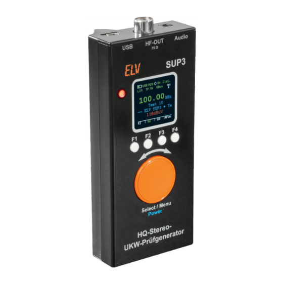
HQ Stereo VHF Test Generator SUP3
The SUP3 generates a high-quality FM signal including an individually configurable RDS signal. In additi-
on to the analogue audio feed, a USB interface also allows digital audio data to be fed in. The operation is
clearly arranged via a practical combination of rotary encoder and OLED display; in addition, PC software
allows easy control of the SUP3 from a PC.
Versatile
After the great response to the predecessor models
SUP1 and SUP2, we present the successor, SUP3, which
has numerous new features. First of all, there is now
Device short description:
Power supply:
Current consumption:
Standby current:
Frequency range:
HF-output:
Audio-inputs:
Display:
Other:
Audio optional analog (audio jack) or digital (USB)
Ambient temperature:
Dimensions (W x H x D):
Weight (with/without batteries):
www.elv.com
2x 1,5 V LR6/Mignon/AA
88–118 dBμV/75 Ω/IEC
Audio-/Stereo-audio-jack
OLED-colour-display with 128 x 128 pixel
Station name (2x 8 characters)
RDS-text (64 characters)
Operation and audio data (digital) via USB
63 x 142 x 25 mm
a digital signal feed via USB. This allows you to use
a PC or other device with USB sound output directly
as a signal source. And since the VHF test generator
can also be operated with batteries and an RDS signal
to be output can be stored in its EEPROM, you can,
SUP3
for example, use the mobile combination of test ge-
nerator and smartphone to put the coveted radio tre-
250 mA max.
asure through its paces before buying it, even if, for
10 μA
example, VHF reception is not possible in a particu-
87,5–108 MHz
lar space. Such a generator is also excellently suited
for demonstrating radios, whether in the showroom
or in a museum, as it makes the radio independent of
antenna reception and also offers the possibility of
outputting your own content, such as explanations in
an exhibition.
However, the main purpose of use is probably the
repair and restoration of VHF radio receivers. An ex-
5 bis 35 °C
act calibration is only possible with a test signal that
conforms to standards. The use as a VHF transmitter,
184/135 g
however, even if it is only for short distances, is pro-
hibited!
Advertisement
Table of Contents

Summary of Contents for elv SUP3
- Page 1 HQ Stereo VHF Test Generator SUP3 The SUP3 generates a high-quality FM signal including an individually configurable RDS signal. In additi- on to the analogue audio feed, a USB interface also allows digital audio data to be fed in. The operation is clearly arranged via a practical combination of rotary encoder and OLED display;...
- Page 2 USB connection. This makes it possible to transfer shielded cable must always be used as the connecting digital audio data from the PC to the SUP3. The SUP3 cable to the device under test and must be connected functions as an external sound card. Remote control directly to the antenna input of the device.
- Page 3 Here it is possible to change the RDS text and the text for the RDS programme service directly. Pressing the Send key transmits the RDS data to the SUP3. If you want to save the texts directly in the SUP3, this is done by pressing the Save to EEprom SUP3 button.
- Page 4 With Auto Power Off you can set a time after which the unit switches vate or deactivate the limiter. The limiter can also be off after the last operation (1‒10 min). With Disable or when supplied via switched with the function key F4. USB, the unit does not switch off automatically. www.elv.com...
- Page 5 The output level is determined by the Circuitry resistor R3, which is 0.6 Vpp in this configuration. This means that the The circuit diagram of the SUP3 (Fig. 8 and 8a) is di- maximum permissible level for the FM transmitter is not exceeded. C7 vided into the following circuit sections: analogue sets the time constant for the control.
- Page 6 BAT54J IRLML IRLML 0,35A IRLML 6401 6401 6401 BAT1 BAT54J 220u 220u 100n MP15 Tantal Tantal 1,5V +5VUSB Mignon +4.4V MP19 BAT2 BC847C IC15 HT-7544-1 MP18 1,5V TPS61040DBV TPS61040DBV Mignon 100n 100n 100n Tantal Figure 8: Circuit diagram SUP3 www.elv.com...
- Page 7 When connected to a PC, an HID device and component contains all the components that are ne- an external sound card are recognised. The SUP3 then works as a sound cessary to generate a standard FM signal. IC12 is a DSP card, while at the same time being operated via USB.
- Page 8 The board is pre-assembled with SMD components so that only a few wired components have to be assem- bled. The wired components are as- Figure 9: Board photos and placement information of SUP3 (Top/ Bottom) www.elv.com...
- Page 9 3 Inserting the OLED-display into the connector 4 Gluing the OLED-display into the frame Figure 11: The individual steps to build the OLED-display – Figure 12: The battery holder ist to be equipped with the battery contacts and the connecting wires www.elv.com...
- Page 10 Now the batteries can be inserted and the board can be placed in the bottom shell of the housing. Finally, both halves of the housing are pushed together. Fig. 16 shows the unit ready for operation. Figure 16: SUP3 Fully assembled and ready for operation www.elv.com...
- Page 11 12 Audio Technology Important notice: More Informations: For the connection between the SUP3 and the [1] https://en.wikipedia.org/wiki/Emphasis_(telecommunications) test object a shielded cable with suitable con- [2] https://en.wikipedia.org/wiki/Frequency_modulation nectors must be used, to prevent any unwanted and not permitted RF radiation.
Need help?
Do you have a question about the SUP3 and is the answer not in the manual?
Questions and answers