Table of Contents
Advertisement
Quick Links
ELECTRIC MINI ATV
OWNER'S MANUAL
Read and understand this entire manual before using!
NOTE: Manual illustrations are for demonstration purposes only.
Illustrations may not reflect exact appearance of actual product.
Specifications subject to change without notice.
OFF ROAD USE ONLY!!!
NEVER OPERATE THIS VEHICLE IF YOU ARE UNDER
AGE 12!!!
- 1 -
Advertisement
Table of Contents

Summary of Contents for Rider Concept ELECTRIC MINI ATV
- Page 1 ELECTRIC MINI ATV OWNER’S MANUAL Read and understand this entire manual before using! NOTE: Manual illustrations are for demonstration purposes only. Illustrations may not reflect exact appearance of actual product. Specifications subject to change without notice. OFF ROAD USE ONLY!!!
-
Page 2: Safety Warnings
16 . Adu lt’s supervision is required if children under age Riding an electric mini ATV can be a hazardous activity. Certain conditions may WARNING: cause the equipment to fail without fault of the manufacturer. Like other electric vehicles, the... - Page 3 age of 12 years is only an estimate, and can be affected by the rider’s size, weight or skills. Any rider unable to fit comfortably on the mini ATV should not attempt to ride it. It is important and necessary to conduct the technical training for your child before first use.
- Page 4 This product was manufactured for performance and durability but are not impervious to damage. Jumping or other aggressive riding can over-stress and damage any product, including the Mini ATV, and the rider assumes all risks associated with high-stress activity. Be careful and know your limitations. Risk of injury increases as the degree of riding difficulty increases.
- Page 5 Use caution when charging. The charger is not a toy. Charger should be operated by an adult. Do not operate charger near flammable materials. Unplug charger and disconnect from bike when not in use. Always disconnect from the charger prior to wiping down and cleaning the vehicle with liquid. FAILURE TO USE COMMON SENSE AND HEED THE ABOVE WARNINGS INCREASES RISK OF SERIOUS INJURY.
- Page 6 Sticker B is located on the right front fender Sticker C is located on the right front fender - 6 -...
- Page 7 Sticker D is located in the chain cover Sticker E is located on the rear swing arm - 7 -...
-
Page 8: Before You Begin
LOCATION OF PIN PIN is stamp marked on an aluminum plate that is riveted on the rear swing arm PIN means the Product Identify Number which is unique for each unit. BEFORE YOU BEGIN Remove contents from box. Remove the foam separators that protect the components from damage during shipping. - Page 9 ·Allen wrench 5mm / 6mm / 10mm ·Bicycle style tire pump with pressure gauge Assembly illustration and instruction ASSEMLY REAR WHEEL A: Nut M16 1pc B: WasherΦ16.5*30*3 1pc C: Rear wheel D: split pin 2pcs E: Rear axle 1. Fix the wheel(C) through the axle. 2.
- Page 10 A: Wheel suspension left and right B: Bolt M10*85*1.5 2pcs C: Nut M10 2pcs 1. Put the front wheel suspension (A) into the front swing arm joint, align the bearing hole to the joint upper and bottom hole. 2. Mount the bolt (B) through the hole and twist the nut (C),tighten it securely with 14mm - 17mm open end wrench and 10mm allen wrench.
- Page 11 A: Nut M8 2pcs B: Bumper C: Bolt M8×16 4pcs 1. Align the bottom mounting hole of bumper (B) to the frame bottom joint and mount the bolt (C), NOT tighten the bolt to keep the bumper free move. 2. Turn upwards the bumper to align the upper mounting hole of bumper to the frame upper joint, then mount the bolt (C) and twist the nut (A).
-
Page 12: Inflating The Tires
A: Bolt M8×50 4pcs B: Upper Clamp C: Bottom Clamp D: handlebar cover E: Handle bar 1. Put the bottom clamp(C) on the steering rod plate with the screw hole in alignment, and place the handlebar (E) in the bottom clamp, then cover the upper clamp (B) on the handlebar and install the 4pcs bolt (A). - Page 13 authorized technician with necessary skills. Tire inflating pressure It is very important to keep the tire in proper pressure and check the tire pressure before use. The inflating should be done while the tire is cold. Tire maintenance Tire tread depth should be checked regularly.( Shallower tread means less grip of tire). You must stop to use the vehicle if the tire is pierced, disassemble the tire and check it carefully.
-
Page 14: Sleep Mode
3-FUNCTION ADJUSTABLE SWITCH The 3-function adjustable switch is located under the seat ( see above picture). There are 3 letters standing for the different functions as follows, Throttle response is adjustable from 0.2S to 1S in clockwise rotation Top speed is adjustable from 8KM /H to 28KM/H in clockwise rotation Motor power output is adjustable from 10A to 35A ( for 48V1300W version, it is adjustable from 10A to 40A) in clockwise rotation SLEEP MODE... - Page 15 OPTIONAL PART 1--- CUT OFF PEDAL & PARKING BRAKE OPTIONAL PART 2---REMOTE CONTROL The remote control unit ( No.1 in above picture) is located under the seat, and the switch Stop the motor: press the button ( No.3 in above picture) Start the motor: quickly press the button 2 times ( No.2 in above picture) Caution: The remote control works effectively within 30 meters only.
-
Page 16: Technical Specification Sheet
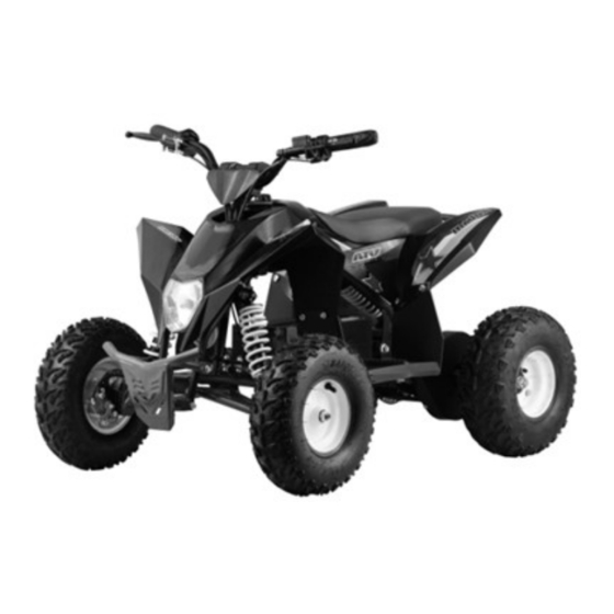
TECHNICAL SPECIFICATION SHEET Motor type 1 1000W 36V Motor type 2 1300W 48V MAX. Power output 1000W36V 1.88KW/1500RPM MAX. Power output 1300W48V 3.30KW/1520RPM Max torque (1000W motor) 10.2Nm /1500RPM Max torque (1300W motor) 18.5 Nm/1520RPM Battery 3 x 12V 12A lead acid battery for 36V 1000W 48V10A / 48V 13A lithium battery for 48V1300W Charger INPUT for 36V lead acid battery 100-240V/50-60 Hz/1.5A... - Page 17 PRODUCT MAIN PART DIAGRAM - 17 -...
- Page 18 1. handlebar cover 2. rear brake lever 3. electricity volume 4. throttle 5. front brake lever 6. rear wheel & tire 7. front swing arm 8. bumper 9. front wheel & tire 10.front lamp 11. ignition switch 12. Forward - Off - Reverse gear switch - 18 -...
- Page 19 13. plastic body 14. rear lamp 15. chain cover 16. rear brake caliper 17. right footrest 18. front shock absorber 19. fuse box 20. battery 21. seat 22. rear rack 23. rear shock absorber 24. motor 25. left footrest - 19 -...
-
Page 20: Before Riding
BEFORE RIDING Charging the Battery Your electric mini ATV may not have a fully charged battery; therefore it is a good idea to charge the battery prior to use. · Initial charge time: 12 hours · Run time: up to 45minutes ·... -
Page 21: Pre-Ride Checklist
Warning: Failure to recharge the battery at least once a month may result in a battery that will no longer hold a charge. PRE-RIDE CHECKLIST Loose Parts Check and secure all fasteners before every ride. Make sure steering stem clamp bolts are locked properly in place. -
Page 22: Adjusting The Brake
Turn power switch off before conducting any maintenance procedures. Adjusting the Brake The mini quad is with 2 front brake and 1 rear brake. WARNING: The brake is capable of causing the electric mini quad to skid the tire throwing an unsuspecting rider. -
Page 23: Replacing The Fuse
3. loosen the chain adjuster nut (C), adjust the chain properly ( refer to the standard: chain can move freely up and down about 4mm), then fasten the nut (C) and (B) Replacing the Fuse WARNING: To prevent shock or short circuit, please follow the instructions accordingly and do not skip or combine any steps. -
Page 24: Battery Care And Disposal
Chain and Sprocket The chain will typically have a “loose spot” and “tight spot” corresponding with a particular sprocket rotational position. This is normal and common to all chain-driven vehicles due to run-out tolerances of the freewheel and sprocket. Proper chain alignment must be maintained. -
Page 25: Troubleshooting Guide
WARNING: To avoid a pinch or injury, keep fingers away from moving sprockets and chain. WARNING: If a battery leak develops, avoid contact with the leaking acid and place the damaged battery in a plastic bag. Refer to the disposal instructions as above. If acid comes into contact with skin or eyes, flush with cool water for at least 15 minutes and contact a physician。... - Page 26 Vehicle was running but Loose wires or connectors. Check all wires and connectors to make sure they are tight. suddenly stopped. Burned-out fuse. The fuse will burn out and automatically shut off the power if the motor is overloaded. An excessive overload could cause the motor to overheat. Refer to replacing the fuse instructions of this manual.
- Page 27 Motor electrical Switch Contact the authorized service center for diagnosis and repair. damage. Charger gets warm During Normal response to Charger use No action required. This is normal for some Chargers and is no cause for concern. If your charger dose not get warm during use, it does not mean that it is not working properly.
-
Page 28: Circuit Diagram
CIRCUIT DIAGRAM - 28 -... - Page 29 Please read the owner’s manual before riding. Never operate this vehicle if you are under age 12. Never use the vehicle on public road. OFF ROAD use only. Never ride with a passenger Always use an approved helmet and protective gear NEVER use with drugs or alcohol Cold tire pressure.
Need help?
Do you have a question about the ELECTRIC MINI ATV and is the answer not in the manual?
Questions and answers