Table of Contents
Troubleshooting

Subscribe to Our Youtube Channel
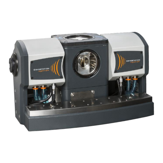
Summary of Contents for Montana Instruments Cryostation s50-MO
- Page 1 4101-DOC001 Option User Manual Magneto-Optic Module Cryostation s50 – MO Version: 2.1 December 2020 www.montanainstruments.com support@montanainstruments.com 101 Evergreen Drive +1.406.551.2796 Bozeman, MT 59715, USA...
- Page 2 This page intentionally left blank.
- Page 3 Montana Instruments. Montana Instruments, Cryostation, nanoReveal, microReveal, Cryo Optic, and ATSM are trademarks of Montana Instruments Corporation. Other brand names used are the property of their respective owners.
-
Page 4: Table Of Contents
Option User Manual Table of Contents Section 1 - Preface ................................ 6 Conventions Used in this Manual ..........................7 1.1.1 Abbreviations ....................................7 1.1.2 Explanation of Safety Warnings ............................. 7 1.1.3 Graphical Symbols ..................................8 General Hazard Information ............................9 Technical Support Information .......................... - Page 5 Magneto-Optic Module 5.1.3 True Zero ...................................... 28 Hall Probe Calibration ..............................29 Section 6 - Maintenance & Troubleshooting ....................... 30 Care & Maintenance Procedures ..........................30 6.1.1 Adding Coolant to the Reservoir ............................30 6.1.2 Coolant Drain Procedure ................................ 32 Diagnostics &...
-
Page 6: Section 1 - Preface
All users must read and understand this manual and all other safety instructions before using the equipment. Retain these instructions for future reference. This manual is intended for users of the Montana Instruments products and systems described herein. Users include anyone who may physically interact with the system or peripheral equipment, including installing, setting up, or configuring the system or anyone who may operate system components via operating panels, the supplied user interface, or remote interfaces. -
Page 7: Conventions Used In This Manual
The following abbreviations may be used: ACM: Ancillary Control Module • CAN: Controller Area Network • DMM: Digital Multimeter • HDMI: High Definition Multimedia Interface • Montana Instruments • PCB: Printed Circuit Board • TCM: Temperature Control Module • User Interface •... -
Page 8: Graphical Symbols
Option User Manual DANGER Serious personal injury Imminent hazards which, if not avoided, will result in serious injury or death. WARNING Serious personal injury Potential hazards which, if not avoided, could result in serious injury or death. CAUTION Possible personal injury Potential hazards which, if not avoided, could result in minor or moderate injury. -
Page 9: General Hazard Information
Magneto-Optic Module 1.2 General Hazard Information The following descriptions are of general hazards and unsafe practices that may result in product damage, severe injury, or death. The products, parts, and components in this manual are to be serviced by authorized Montana •... -
Page 10: Technical Support Information
Montana Instruments service representative. 1.3.1 Warranty & Repairs If the system or parts need to be returned to the Montana Instruments factory or an authorized service center for repair or service, contact an authorized service representative for a return merchandise authorization (RMA) number and instructions on returning the unit. -
Page 11: Section 2 - Option Overview
Top View of Magneto-Optic 2.1.1 Intended Use The Magneto-Optic module is an add-on option for the Montana Instruments Cryostation s50 model that integrates a bipolar electromagnet with the sample space. The assembly allows the user to place their sample between the magnet poles above the cryogenic platform. - Page 12 The two lower DSUB9 ports on the rear face of the enclosure are to be used only with expansionary devices and accessories offered by Montana Instruments. For more information about the usage and capabilities of these ports, contact an authorized service representative.
-
Page 13: Technical Specifications
Magneto-Optic Module DSUB13W3 ( MAGNET INTERCONNECT A combination 13W3 combination D-Subminiature port is used to connect the electromagnet housing and power supply. This connection provides the field current and monitors temperature of the electromagnet housing. Hall Probe Sensor A Hall probe sensor is provided for running calibration routines on the unit. The Hall probe sensor fits onto the top of the magnet housing and connects to the front of the power supply via the supplied cable. -
Page 14: Performance Data
Option User Manual Magneto-Optic Specifications Field With 12 mm Pole Tips Range -0.7 to 0.7 Tesla Resolution <5 µTesla Accuracy <2% of Range NOTE 1 NOTE 2 Noise and Ripple <10 µTesla Uniformity Axial 1% - ±0.1 inch from Center; 0.1% - ±.05 inch from Center Radial 1% - ±0.25 inch from Center;... - Page 15 Magneto-Optic Module Figure 2: Radial Field Uniformity, 0.1% uniformity at 4mm for ±4mm from center Figure 3: X distance from center field uniformity, 1% uniformity at ±4mm, and 0.1% uniformity at ±4.5mm...
- Page 16 Option User Manual Figure 4: Field vs. Current for various pole spacings* » NOTE *Pole tip spacing of <5mm will increase base temperature To achieve a 5mm pole tip spacing, the radiation shield will need to be removed. Doing so will increase the base temperature by several Kelvin.
-
Page 17: Safety Information
Magneto-Optic Module 2.1.5 Safety Information The following hazards may be typical for this product: The module must be used in a normal condition only in which all means of protection are intact. • WARNING Strong static magnetic field: Potential hazards of magnetic origin may result in minor to moderate injury and/or equipment damage. - Page 18 Option User Manual WARNING High voltage: danger of electric shock Electric shocks and burns from capacitor discharge or power circuits could lead to serious injury or death. Prior to accessing the enclosure or when otherwise servicing the unit (authorized service •...
-
Page 19: Section 3 - Option Installation & Handling
Magneto-Optic Module Section 3 - Option Installation & Handling 3.1 Packaging Contents The Magneto-Optic components will arrive packed on their own pallet. One box contains the electromagnet, cables, and magnet accessories. The other box contains the power supply. The electromagnet is shipped within a protective hard case that can be re-used for storage or transport. NOTICE Inspect shipment upon receipt Before unpacking the system, please note the condition of the... -
Page 20: Connecting System Cables And Power
Option User Manual 3.4 Connecting System Cables and Power NOTICE Only use cables and hoses provided or approved by the manufacturer Only use the cables and hoses in the manner described below. Other than the DSUB9 compressor communication cable, the standard communication cables and hoses between system components do not change. - Page 21 Magneto-Optic Module Magnet Interconnect: 3. Locate the DSUB13W3 combination M-F cable. Connect the F end to the MAGNET INTERCONNECT location on the back of the power supply. Connect the M end to the connection point on the back side of the electromagnet assembly. Fully tighten the retaining screws on both connections with a screwdriver to secure.
-
Page 22: Section 4 - Option Configuration
Option User Manual Section 4 - Option Configuration Refer to the System User Manual for instructions on unpacking, mounting, and installing the cryostat. Complete these steps before configuring the Magneto-Optic. NOTICE Keep sample chamber and surfaces clean Always wear sterile gloves when working in the sample chamber to avoid getting oils on the •... - Page 23 Magneto-Optic Module a. Check to ensure there are no wires or components touching the inside of the radiation shield. Adjust if necessary. 3. Press the upper portion of the radiation shield into place on top of the lower radiation shield. a.
- Page 24 Option User Manual » NOTE If the yoke does not sit flat on the optical table when the magnet is set into place: 1. Loosen the two lower screws on either side of the assembly slightly (indicated red in figure to the right). 2.
- Page 25 Magneto-Optic Module 7. Place the vacuum housing lid on top of the sample chamber. Step 7 Installing the Magnet Housing without Yoke If a side panel or other connector obstructs the ability to lift the magnet housing onto the sample platform, the yoke can be removed and re-installed once the magnet is seated.
-
Page 26: Installing Or Changing Pole Tips
Option User Manual 4.1.2 Installing or Changing Pole Tips The pole tips are removable and slide in and out of the magnet on a grooved attachment point inside the vacuum housing. 1. To slide the poles into place, start with the pole directly over the attachment location and slide straight down into the groove until seated. -
Page 27: Section 5 - Option Usage & Operation
Magneto-Optic Module Section 5 - Option Usage & Operation 5.1 Primary Operations The primary operations below cover magnet-specific settings for the instrument. Refer to the System User Manual for detailed user interface control functions. 5.1.1 Turning on the System The magnet power supply can be turned on before or after powering on the other components. To turn on the power supply, toggle the power switch on the back of the unit ON ( | ). -
Page 28: True Zero
Option User Manual The name of the current calibration and the maximum field strength available for that calibration will be shown above the magnetic field gauge at the top of the UI. Setting a Target Field The magnetic field can be controlled by setting a specific target value. 1. -
Page 29: Hall Probe Calibration
Magneto-Optic Module 5.2 Hall Probe Calibration NOTICE Only use the Hall probe sensor provided by the manufacturer • Never insert any other connector into the port on the front of the power supply • HALL SENSOR Installing the Hall Probe Sensor To run a calibration routine, first install and connect the Hall probe sensor. -
Page 30: Section 6 - Maintenance & Troubleshooting
Option User Manual Section 6 - Maintenance & Troubleshooting 6.1 Care & Maintenance Procedures WARNING Risk of serious injury due to coolant exposure The coolant consists of Koolance low electrical conductivity liquid coolant. The coolant contains propylene glycol. Coolant may cause serious irritation to the eyes and skin. Wear protective gloves, clothing, and •... - Page 31 Magneto-Optic Module The orientation of the filling adapter hose is not important. This adapter will reduce the amount of air through the lines during the initial fill of the power supply. Pressure relief cap / fill port Adapter hose connected to supply and return 4.
-
Page 32: Coolant Drain Procedure
Option User Manual 9. Once the lines and cables are connected, turn the power supply back on by toggling the power switch on the back of the unit ON ( | ). The coolant level will drop substantially as the coolant lines and magnet fill. - Page 33 Magneto-Optic Module Gravity drain on return connection Gravity drain on supply connection 5. When most of the coolant is drained from the reservoir, disconnect the drain adapter hose. 6. Repeat steps 3-5 for the connection. COOLANT SUPPLY 7. Verify that the coolant level indicator on the front panel reads empty. Then, disconnect the drain adapter hose and replace the fill port pressure relief cap.
- Page 34 Option User Manual b. Connect the female connector of the drain adapter hose to the COOLANT RETURN location on the back of the power supply. Connect the other end to a nitrogen source via the adapter. Ensure the nitrogen source is off before connecting. c.
- Page 35 Magneto-Optic Module Part 3: Distilled Water Flush 16. Disconnect both adapter hoses. Then, reconnect the supply and return coolant lines to the locations on the back of the power supply. COOLANT SUPPLY COOLANT RETURN 17. Unscrew the fill port pressure relief cap at the top front of the power supply. Fill the reservoir with 1-liter of distilled water and replace the cap.
-
Page 36: Diagnostics & Troubleshooting
Option User Manual NOTICE Use new storage vessel for the second and third flush If you would like to save and re-use the original coolant drained during the first flush, use a different storage vessel for the second and third flush when the drained substance is primarily distilled water. Coolant and contaminated water require proper disposal Dispose of all drained substances per local regulations. -
Page 37: Section 7 - Appendices
Magneto-Optic Module Section 7 - Appendices 7.1 Related Documentation For a copy of associated documentation, see below: Document Document Title Location Number 4100-DOC001 System User Manual: www.montanainstruments.com/library/files/4100- Cryostation s-series DOC001.pdf DOC102 General Terms and www.montanainstruments.com/About/Terms Conditions of Sale DOC103 Limited Warranty Agreement www.montanainstruments.com/About/Warranty DOC104 End User License Agreement... - Page 39 Notes...
- Page 40 © Montana Instruments® Corporation, All Rights Reserved...
Need help?
Do you have a question about the Cryostation s50-MO and is the answer not in the manual?
Questions and answers