
Subscribe to Our Youtube Channel
Summary of Contents for Standard IGL15
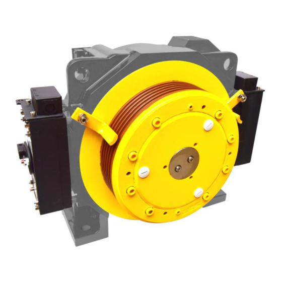
- Page 1 IGL15 Permanent magnet synchronous elevator traction machine Product Operation and Maintenance Manual S2018.05...
-
Page 2: Table Of Contents
IGL15 Spare parts replacement manual Catalogue ATALOGUE ............................1 PREFACE ............................2 1.1......................2 AFETY ECLARATION 1.2. IGL15 ................2 TRACTION MACHINE SPARE PARTS LIST SPARE PARTS REPLACEMENT OPERATION ............... 3 2.1....................3 RACTION WHEEL REPLACEMENT 2.1.1. Remove the traction sheave ..................... 3 2.1.2. -
Page 3: Preface
No liability can be assumed for any damage caused by improper handling or any other acts, which are not in conformity with these operating instructions and thus deter from the qualities of the product. 1.2. IGL15 traction machine spare parts list Part No. Name Remark IGL15.1.1-1... -
Page 4: Spare Parts Replacement Operation
IGL15 Spare parts replacement manual V4NSY10 Micro-Switch 1000mm(UL) 2. Spare Parts Replacement Operation 2.1. Traction wheel replacement Remove the traction sheave 2.1.1. 1. Loosen nut M12 and washer 12 with an open wrench (18 mm) and remove the swing bar. Loosen nut M12 and washer 12 with an open wrench (18mm), and remove screw M12×55 with a hexagon wrench (10mm). - Page 5 IGL15 Spare parts replacement manual Bolt M12×40 Washer M12 Pin 12 3. Remove the bolt M12×50 from the threaded hole in the traction wheel 2-m12, and tighten the bolt diagonally with an open wrench (18mm) until the traction wheel and pin 12 are pushed out and the traction wheel is removed.
-
Page 6: Install The Traction Sheave
IGL15 Spare parts replacement manual Install the traction sheave 2.1.2. 1. Clean the matching surface of brake wheel and traction wheel. Screw two pieces of screw M12×100 diagonally inside the screw hole of the traction wheel, and then install the traction wheel through the screw M12 onto the brake wheel, and slowly press the traction wheel into the brake wheel with bolt M12×80. - Page 7 IGL15 Spare parts replacement manual Bolt M12×40 Washer 12 3. Lift the tractor into a vertical position with lifting equipment and rotate the traction wheel for more than 1 week.Testing with dial indicator: the normal runout of the groove surface of the traction wheel is ≤0.12mm. Meanwhile, components are required: the rotor rotates flexibly, the bearing has no noise, and the rotor and stator have no interference.
-
Page 8: Encoder Replacement
IGL15 Spare parts replacement manual 2.2. Encoder Replacement Suggestion: before changing the encoder, wear the antistatic bracelet on the wrist Remove the encoder ERN1387 2.2.1. 1. Remove the encoder cover. Encoder cover 2. Loosen the screw of the back cover of the encoder with hexagon wrench (4mm) and remove the back cover of the encoder. - Page 9 IGL15 Spare parts replacement manual 3. Remove the encoder lead. Encoder lead 4. Loosen the set screw M2.5 of the encoder housing with an hexagon wrench (2mm), and loosen the screw M5×50 with an hexagon wrench (4mm). Set screw M2.5 Screw M5×50...
-
Page 10: Install The Encoder Ern1387
IGL15 Spare parts replacement manual 5. If the unscrewed screw M5×50 cannot be removed from the encoder, screw the screw M5×50 back into the encoder, tighten it with hexagon socket wrench (4mm), release 1-2 turns (counterclockwise rotation of 360° -720 °), then screw the screw M10×50 into the encoder, and tighten it with hexagon socket wrench... - Page 11 IGL15 Spare parts replacement manual Encoder Bolt M5×50 3. Use hexagon wrench (2mm) encoder housing set screw M2.5, and use torque wrench to confirm that the tightening torque is 1.25Nm (lock the set screw in the horizontal direction, the position is on the right). Plug in the encoder lead.
- Page 12 IGL15 Spare parts replacement manual 4. Plug in the encoder lead. Install the back cover of the encoder to the end face of the encoder, fix it with the screw M5 of the back cover of the encoder, tighten it with hexagon wrench (4mm), and confirm with torque wrench that the tightening torque is 5Nm.
-
Page 13: Bearing 6212-2Rs Replacement
2.3. Bearing 6212-2RS Replacement Remove the bearing 6212-2RS 2.3.1. 1. Remove the encoder (refer to IGL15 spares replacement manual for permanent magnet synchronous elevator tractor - encoder replacement method). Loosen screw M5×12 and washer 5 with hexagon wrench (4mm) and remove encoder cover and waveform spring 120. - Page 14 IGL15 Spare parts replacement manual 4. Loosen screw M8×25 with socket wrench (5mm) and remove gland. Bolt M8×25 Gland 5. Install the pull body to the end of the traction wheel, fix it with two bolts M12×30, and tighten it with an open spanner (18mm). Then screw in the pull body with an open wrench (36mm) bolt M24×200.Slowly tighten bolt M24×200 with an open...
- Page 15 IGL15 Spare parts replacement manual Spindle assembly 7. Use the bearing remover to pull the bearing 6213-2rs out of the main shaft bearing block. Bearing 6213-2RS Bearing puller Version:S2018.05...
-
Page 16: Install The Bearing 6212-2Rs
IGL15 Spare parts replacement manual Install the bearing 6212-2RS 2.3.2. 1. Clean the main shaft bearing gear, put the bearing 6213-2rs into the main shaft bearing gear, and then put the bearing 6213 pressure sleeve on, hit it in place with a copper hammer, and then use the retainer pliers to load the retainer 65 into the main shaft bearing gear, and fix the inner ring of the bearing. - Page 17 IGL15 Spare parts replacement manual 4. Apply an appropriate amount of TONSAN 1243 thread adhesive to the corresponding screw hole of screw M8×25, install the gland to the end face of brake wheel, fix it with screw M8×25, tighten it with hexagon wrench (5mm), and confirm with torque wrench that the tightening torque is 20Nm.
-
Page 18: Bearing 6317-2Rs/C3 Replacement
Remove encoder (refer to IGL15 permanent magnet synchronous elevator tractor spare parts replacement manual - encoder replacement method). Remove encoder sheath, main shaft back end cover, wave spring 120 (refer to IGL15 permanent magnet synchronous elevator tractor spare parts replacement manual - bearing 6212-2rs replacement method) Remove the nylon cover with a screwdriver. - Page 19 IGL15 Spare parts replacement manual Bolt M8×25 7. Loosen bolt M8×25 with socket wrench (5mm) and remove gland. Bolt M8×25 gland 8. Install the lifting ring assembly to the brake wheel end and fasten it with bolt M12×25. Brake wheel sling Bolt M12×25...
- Page 20 IGL15 Spare parts replacement manual 9. Install guide shaft in the bearing hole of the frame. Remove the nylon cover with a screwdriver. Nylon cover Guide shaft 10. Screw two pieces of screw M12×1.5×400 diagonally into the corresponding screw hole of the machine base.Pull the body (rotor assembly removed) through the screw to the appropriate position, fixed with nut M12×1.5.Put the jack in the...
- Page 21 IGL15 Spare parts replacement manual Bearing 6213-2RS Retainer65 Retainer85 12. Lift up the brake wheel assembly, insert two screw M12×300 diagonally into the corresponding screw hole of the rotor assembly, pass the pull body through the screw to the appropriate position, and fix it with nut M12. Remove the tooling from the jack and bearing 6317 and put it in the position shown in the figure.
-
Page 22: Install Bearing 6317-2Rs/C3
IGL15 Spare parts replacement manual Install bearing 6317-2RS/C3 2.4.2. 1. Deburr and clean the rotor bearing gear. Place the outer gland into the inner hole of the rotor assembly. 2. Screw the small head into the screw M8×500.As shown, and then three pieces of screw M8 together through the brake wheel 3 - M20 hole at the bottom of the outer gland 3 - Φ... - Page 23 IGL15 Spare parts replacement manual 3. Install the rear-ring 85 into the rear-ring groove corresponding to the brake wheel with circlip clamp, and fix the bearing 6317. Put the bearing 6213 into the main shaft bearing gear, put the bearing 6213 pressure sleeve, and hit it in place with a copper hammer.
- Page 24 IGL15 Spare parts replacement manual 6. Drive the traction wheel to find the matching screw hole between the outer gland and the frame. Tighten the outer gland and the machine base (screw should be tightened diagonally) with anti-falling screw M8×25 (or coated with TONSAN 1243 thread glue), with a tightening torque of 20Nm.Install the nylon cover to the...
- Page 25 IGL15 Spare parts replacement manual Gland Screw M8 x 25 8. Install corrugated washer 120 and encoder cover (refer to IGL15 permanent magnet synchronous elevator tractor spare parts replacement manual - bearing 6213-2rs replacement method). 9. Install encoder (refer to IGL15 permanent magnet synchronous elevator spare parts replacement manual - encoder replacement method).
-
Page 26: Brake Fzd10 Replacement And Adjustment ( Shown As The Right Side Brake )
IGL15 Spare parts replacement manual 2.5. Brake FZD10 Replacement and Adjustment (shown as the right side brake) Remove the FZD10 brake 2.5.1. 1. Remove the brake double diagonal screw M8×100 with hexagon wrench (6mm). Screw M8×100 Brake 2. Screw the stud M8×130 into the two diagonal screw holes. - Page 27 IGL15 Spare parts replacement manual 3. Remove the remaining screw M8×100 with hexagon socket wrench (6mm). Screw M8×100 Stud M8×100 4. Remove the brake, remove the stud M8×130. Screw M8×100 Brake Version:S2018.05...
-
Page 28: Install The Fzd10 Brake
IGL15 Spare parts replacement manual Install the FZD10 brake 2.5.2. Clean brake wheel surface and brake installation surface by ethanol Screw stud bolts M8×130 into diagonal thread holes Version:S2018.05... - Page 29 IGL15 Spare parts replacement manual Install brake through studs M8×130. Screw and tighten two bolts M8×100 with the inner hexagon spanner(6mm), coated with TONSAN 1243 thread sealant, into thread holes left. Remove the studs M8×130, instead, screw and tighten two bolts M8×100 with the inner hexagon spanner(6mm), coated with TONSAN 1243 thread sealant.
- Page 30 IGL15 Spare parts replacement manual Adjust the spacer, and make each spacer has no contact with the brake and the machine case. Adjust(tighten or loosen) the bolt M8×100, make the gap between the static plate and the dynamic plate: 0.30mm.(Attention: the gap position shown as the picture below; adjust and check the No.2 and the No.4 at first, then the No.3 and No.1).
- Page 31 IGL15 Spare parts replacement manual 0.30-0.40mm Remarks:the position No.1,No.2,No.3,No.4 is at the middle of the bolt M8×100 and bolt M6×60. Power on and test the traction machine Version:S2018.05...
-
Page 32: Adjust Brake Noise
IGL15 Spare parts replacement manual Adjust brake noise 2.5.3. 1. Check whether the gap between the moving iron core and the static iron core of the brake meets the requirements. 2. Measure brake noise ≤65dB(A) with decibel meter; If noise > 65dB(A), loosen nut M6 with a dummy wrench (10mm), and screw out four screws (M6×60) with an hexagon wrench... -
Page 33: Brake Rubber Assembly Replacement
Remove the brake rubber assembly 2.6.1. FZD10 1. Remove brake (Refer to IGL15 permanent magnet synchronous elevator tractor spare parts replacement manual - brake FZD10 replacement and adjustment method). 2. Remove bolts M5×16 with the inner hexagon spanner(4mm), and take down brake rubber assembly... -
Page 34: Install The Brake Rubber Assembly
IGL15 Spare parts replacement manual Install the brake rubber assembly 2.6.2. Clean contact surface of brake and brake rubber assembly by ethanol. Contact surface brake and brake rubber assembly by ethanol Install brake rubber assembly on brake, tighten bolt M5×16 with the inner hexagon spanner (4mm), coated with TONSAN 1243 thread sealant, with torque 3.5-4Nm. -
Page 35: Stroke Switch Replacement
IGL15 Spare parts replacement manual 2.7. Stroke Switch Replacement Remove the stroke switch assembly 2.7.1. 1. Release the lead of travel switch. Remove knurled screw M5x10, and take down stroke switch plate assembly. Knurled screw M5x10 Stroke switch plate assembly... - Page 36 IGL15 Spare parts replacement manual , Loosen the nut M4 and washer 4 with the open-ended spanner(7mm) Remove stroke switch contact panel. M5×10 and washer 5 with the cross screwdriver wrench(6×125) Remove bolt take down stroke switch assembly. Remove nut M4 with the open-ended spanner (7mm), take down stroke switch.
-
Page 37: Install The Stroke Switch Assembly
IGL15 Spare parts replacement manual Install the stroke switch assembly 2.7.2. Install stroke switch contact panel on stroke switch plate, tighten bolt M4×10 and washer 4 with the open-ended spanner(7mm). Install stroke switch on stroke switch bracket, tighten nut M4 with the open-ended spanner (7mm) Version:S2018.05... - Page 38 IGL15 Spare parts replacement manual Install stroke switch assembly assembled at previous step on traction machine, tighten bolt M5×10 and washer 5 with the cross screwdriver wrench(3×75) 4. Install the contact plate assembly of the travel switch to the corresponding screw hole on the end face of the machine base and fix it with knurled flat head screw M5×10.
-
Page 39: Micro-Switch Replacement
IGL15 Spare parts replacement manual 2.8. Micro-Switch Replacement Remove the Micro-Switch assembly 2.8.1. Take down junction box cover. Version:S2018.05... - Page 40 IGL15 Spare parts replacement manual Unlock connecting terminal with the straight screwdriver(3×75) , pluck out the cable Bk+、 Bk-、NO、NC、COM in order. Remove bolt M3×8 and washer 3 with the cross screwdriver wrench(6×125), and take down connecting terminal. Remove bolt M6×14 and washer 6 with the open-ended spanner(10mm) , and take down dust guard plate.
- Page 41 IGL15 Spare parts replacement manual Remove bolt M2×10 with the cross screwdriver wrench ( 6×125) , and take down dust guard plate and micro-switch . Version:S2018.05...
-
Page 42: Install And Adjust The Micro-Switch Assembly
Micro-switch adjustment Check:make sure that the gap between the static plate and the dynamic plate: 030-0.40mm. (refer to IGL15 permanent magnet synchronous elevator tractor spare parts replacement manual - brake FZD10 replacement and adjustment method) Connect the stylus of multimeter with the exit wire of micro switch (NO, COM), and dial the multimeter to the corresponding gear position. - Page 43 IGL15 Spare parts replacement manual Adjustment:Loosen the nut M5. If the gap A is <0.65mm, loosen the bolt M5×30 with the open-ended spanner ( 8mm) (screw it clockwise); If the gap is >0.85mm, tighten the bolt M5 ×30 with the open-ended spanner( 8mm) (screw it anticlockwise), adjust(tighten or loosen) the bolt until it satisfies the requirement above.
- Page 44 IGL15 Spare parts replacement manual (3×75) Unlock connecting terminal by slotted screwdriver . Plug brake cables into connecting terminal in the order Bk+、 Bk-、 NO+、 NO-、COM. Remove slotted screwdriver, lock connecting terminal by itself, make sure that each cable connects well Install junction box cover, tighten tapping screws.
- Page 45 IGL15 Spare parts replacement manual Power on and test traction machine. Version:S2018.05...
Need help?
Do you have a question about the IGL15 and is the answer not in the manual?
Questions and answers