
Related Manuals for SGM LEKTRA RSL200

Summary of Contents for SGM LEKTRA RSL200
- Page 1 RSL200 vibration level switch, with rigid and semi-fl exible extension for bulk solids and powders. technical documentation EN Rev. M...
-
Page 2: Table Of Contents
RSL200 - contents CONTENTS 1-WARRANTY page 3 2-PRODUCT page 4 3-TECHNICAL SPECIFICATIONS page 5 4-DIMENSIONS page 6 5-INSTALLATION page 7 6-ELECTRICAL CONNECTIONS page 10 7-LOCAL OPERATOR INTERFACE (LOI)-VL601 page 11 8-PARAMETER PROGRAMMING page 12 9-TESTING AND QUALITY CERTIFICATE page 16 Page 2 of 16 www.sgm-lektra.com... -
Page 3: 1-Warranty
RSL200 - warranty 1-WARRANTY Products supplied by SGM LEKTRA are guaranteed for a period of 12 (twelve) months from delivery date according to the conditions specifi ed in our sale conditions document. SGM LEKTRA can choose to repair or replace the Product. -
Page 4: 2-Product
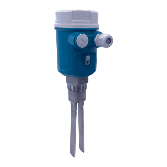
RSL200- product 2- 2- PRODUCT 1. Cover 2. VL601 (opt.) 3. Skintop M20 4. Process connection 5. Forks 6. Anti-condensate fi lter IDENTIFICATION Every instrument has an adhesive identifi cation plate on which the main information about the meter is outlined. -
Page 5: 3-Technical Specifications
RSL200 - technical specifi cations 3-3- TECHNICAL SPECIFICATIONS Casing material PC/AL Vibrating prong material AISI316 (AISI304 for semi-fl exible extension tube) Protection rating IP67/IP68 in process Pressure -1 ÷ +6bar Ambient temperature -20 to +60°C Max. process temperature 150°C Power supply 24Vdc ÷... -
Page 6: 4-Dimensions
RSL200 - dimensions 4-4- DIMENSIONS 5.1 MECHANICAL DIMENSIONS Ø95 Ø95 1"½ G 1"½ G Ø95 1"½ G Ø12 Page 6 of 16 www.sgm-lektra.com... -
Page 7: 5-Installation
PRECAUTIONS FOR INSTALLATION 5.1.1 CORRECT INSTALLATION Correct installation of RSL200 sensors to control a Max. level (“a” and “c”) and Min. level (b). To avoid triggering problems, follow the instructions below: - Install away from loading zones and keep a minimum distance of 300mm from the walls of the tank. - Page 8 • do not install at the centre of the tank loading point (d); the RSL200 sensors and/or ceiling of the tank may be damaged and eventually break the RSL200 sensor, due to the elevated mechanical stress created in this point.
- Page 9 RSL200 - installation 5.1.3 Semifl ex Extension Bent extension (h) (g) The extension must be straightened (i) to prevent the sensitive element from touching the wall of the tank and sending a false ‘product present’ signal: false max. level alarm or, vice versa, failed min. level alarm signal.
-
Page 10: 6-Electrical Connections
RSL200 - electrical connections 6-ELECTRICAL CONNECTION CONNECTIONS 1) Before energizing this product, make sure all connections have been correctly made and that the mains voltage corresponds to that on the rating plate. 2) Tighten the cable glands and cover to ensure a protection rating of IP67. -
Page 11: 7-Local Operator Interface (Loi)-Vl601
The RSL200 vibration level checks are programmed and calibrated using the VL601 display module VL601 FEATURES The VL601 programming module can be activated and deactivated on-board the RSL200 without aff ecting the unit’s operation. The VL601 module is equipped with an LCD dot-matrix display and allows simple and fast start-up using the 4 programming keys. -
Page 12: 8-Parameter Programming
RSL200 - parameter programming 8-PARAMETER PROGRAMMING 8.1 TH 0350 Press ENTER to modify the programming. DELAY: 00 S Using the UP ARROW adjust the limit from 0 to 1000: MODE: MAX during programming a “transparent” cursor will be displayed, which indicates the new positioning of the level alarm limit. - Page 13 RSL200 - parameter programming By setting the MODE parameter with the “MAX” option, the RSL200 sensors will work in maximum level alarm mode: - normal condition; relay energized in absence of product - alarm condition; relay de-energized in presence of product...
- Page 14 RSL200 - notes NOTES ____ ____________________________________________________________________________________________________ _______________________________________________________________________________________ _______________________________________________________________________________________ _______________________________________________________________________________________ _______________________________________________________________________________________ _______________________________________________________________________________________ _______________________________________________________________________________________ _______________________________________________________________________________________ ____________________________________________________________________ ______________________ ______________________ ______________________________________________________________________________ ________________________________________________________________________________________ ________________________________________________________________________________________ ________________________________________________________________________________________ ________________________________________________________________________________________ ________________________________________________________________________________________ ________________________________________________________________________________________ ________________________________________________________________________________________ ___________________________________________ _____________________________________________________ _________________________________________________ _______________________________________________ ________________________________________________________________________________________ ________________________________________________________________________________________ ________________________________________________________________________________________ ________________________________________________________________________________________ ________________________________________________________________________________________ ________________________________________________________________________________________ ________________________________________________________________________________________ ________________ _____________________________________________________________________________________ ___________________________________________________________________________ _______________ ________________________________________________________________________________________...
- Page 15 Page 15 of 16 www.sgm-lektra.eu...
-
Page 16: 9-Testing And Quality Certificate
Documentation subject to technical change with no prior warning 10-FACTORY TEST AND QUALITY CERTIFICATE In conformity to the company and check procedures I certify that the equipment: (Vibration probe) (Electronic Unit) is conform to the technical requirements on Technical Data and it is made in conformity to the procedure Quality Control Manager: ............
Need help?
Do you have a question about the RSL200 and is the answer not in the manual?
Questions and answers