
Related Manuals for Elstat ems75vr


Summary of Contents for Elstat ems75vr
- Page 1 Royal Vending Installation and User Guide Elstat, Astra Business Centre, Roman Way, Preston, Lancashire, PR2 5AP, United Kingdom Telephone: +44 161 22 77 200 www.elstatgroup.com...
-
Page 2: Table Of Contents
Before installation --------------------------------------------------------------------------------------------------------------------------- 5 Install the ems75vr ----------------------------------------------------------------------------------------------------------------------------- 6 ems75vr installation ------------------------------------------------------------------------------------------------------------------------ 6 How to install the ems75vr ---------------------------------------------------------------------------------------------------------------- 6 How to connect to the compressor ------------------------------------------------------------------------------------------------------ 7 How to connect to the mains supply ---------------------------------------------------------------------------------------------------- 9 How to connect to the lights ------------------------------------------------------------------------------------------------------------ 11... - Page 3 Annex – UL information --------------------------------------------------------------------------------------------------------------------- 26 Additional information ------------------------------------------------------------------------------------------------------------------- 27 Parameter set ---------------------------------------------------------------------------------------------------------------------------------- 28 For use with the following models: RVCCR-550, RVCCR-660, RVCCR-780, RVCCR-804, RVCC-550, RVCC-660, RVCC-780, and RVCC804 THURSDAY, 27 FEBRUARY 2014 PAGE 3 OF 31 EMS75VR-ROYAL-VENDING-INSTALLATION AND USER GUIDE-ISS3...
-
Page 4: Installation Requirements
Installation requirements 1.1 Wiring harness The ems75vr is provided with a wiring harness that is suitable for internal wiring only. The mounting, secureness, segregation requirements and acceptability of the wiring harness are to be investigated and considered under the requirements of the ultimate end-use application. -
Page 5: Tools Required
Cable ties must not be used to secure the sensor head. This will invalidate the warranty. 1.5 Before installation The vending machine should be checked to ensure that it is in good working order before the ems75vr kit is installed. -
Page 6: Install The Ems75Vr
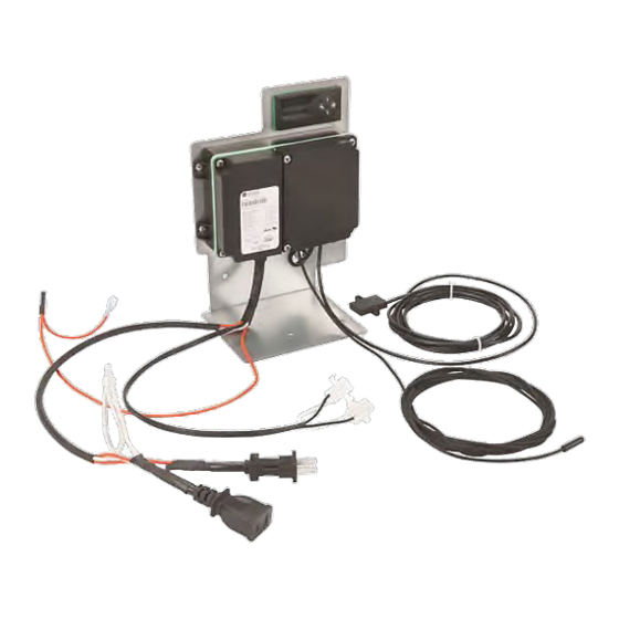
Install the ems75vr 2.1 ems75vr installation Mount the bracket fitted with the ems75vr controller and remote display in the base of the vending machine. Then, connect the ems75vr controller to the mains supply, compressor, and lights. 2.2 How to install the ems75vr Install the ems75vr as follows: Ensure that the mains supply is switched off. -
Page 7: How To Connect To The Compressor
Secure the bracket using the two no.8 self-drilling screws (supplied) as shown below. 2.3 How to connect to the compressor Connect the ems75vr to the compressor as follows: Identify the mains compressor cable and connector as shown below. Disconnect the compressor plug as shown below. - Page 8 Identify the compressor plug and socket on the wiring harness of the ems75vr as shown below. Unplug compressor plug and connect the ems75vr plug to the compressor socket and the ems75vr socket to the compressor plug as shown below. THURSDAY, 27 FEBRUARY 2014...
-
Page 9: How To Connect To The Mains Supply
Connect the ems controller to the mains supply as follows: Identify the mains filter as shown below. Cut the insulation of the wiring harness live (red) wire as shown below. THURSDAY, 27 FEBRUARY 2014 PAGE 9 OF 31 EMS75VR-ROYAL-VENDING-INSTALLATION AND USER GUIDE-ISS3... - Page 10 Connect the single red wire of the supplied power jumper to the filter and reconnect the smooth black wire to the other end of power jumper as shown below. THURSDAY, 27 FEBRUARY 2014 PAGE 10 OF 31 EMS75VR-ROYAL-VENDING-INSTALLATION AND USER GUIDE-ISS3...
-
Page 11: How To Connect To The Lights
2.5 How to connect to the lights Connect the ems controller to the lights as follows: Identify the lights connector. Disconnect the lights connectors as shown below. THURSDAY, 27 FEBRUARY 2014 PAGE 11 OF 31 EMS75VR-ROYAL-VENDING-INSTALLATION AND USER GUIDE-ISS3... - Page 12 Connect the lights jumper from the ems as shown below. THURSDAY, 27 FEBRUARY 2014 PAGE 12 OF 31 EMS75VR-ROYAL-VENDING-INSTALLATION AND USER GUIDE-ISS3...
-
Page 13: Mount The Motion Sensor
Install the motion sensor as follows: Route the motion sensor from the ems75vr through the vending machine door as shown below. Route the motion sensor over the top of the chute and then through the small hole on the top of the chute as shown below. - Page 14 Pass the motion sensor cover over the cable and connect the cable to the motion sensor as shown below. Then, clip the cover into position. THURSDAY, 27 FEBRUARY 2014 PAGE 14 OF 31 EMS75VR-ROYAL-VENDING-INSTALLATION AND USER GUIDE-ISS3...
- Page 15 Use an appropriate drill bit to drill two holes to mount the motion sensor with two no. 4 self-tapping screws (supplied) as shown below. Use the two self-tapping screws to secure the motion sensor in position as shown below. THURSDAY, 27 FEBRUARY 2014 PAGE 15 OF 31 EMS75VR-ROYAL-VENDING-INSTALLATION AND USER GUIDE-ISS3...
-
Page 16: Mount The Appliance Sensor
Identify the access cover that allows cable to be passed between the compressor and refrigeration compartments. Remove the screw from one side of the cover and loosen the screw on the other side as shown below. THURSDAY, 27 FEBRUARY 2014 PAGE 16 OF 31 EMS75VR-ROYAL-VENDING-INSTALLATION AND USER GUIDE-ISS3... - Page 17 Open the cover and pass the appliance sensor cable from the ems75vr to the refrigeration compartment as shown below. Place the appliance sensor approximately 1 to 2 inches from the evaporator as shown below. THURSDAY, 27 FEBRUARY 2014 PAGE 17 OF 31...
- Page 18 Refit the access cover as shown below. THURSDAY, 27 FEBRUARY 2014 PAGE 18 OF 31 EMS75VR-ROYAL-VENDING-INSTALLATION AND USER GUIDE-ISS3...
-
Page 19: Ems75Vr Wiring Diagram
The wiring diagram for the ems75vr controller is shown below. ems75vr lights in pin 1 remote display lights lights out pin 1 appliance sensor compressor in microRMD condenser compressor out compressor straight neutral receptical live in cooler... -
Page 20: How To Run The Test Routine
How to run the test routine 6.1 Test routine The user interface for the ems75vr is as follows: Defrost Down The LED indicators are as follows: Saving temperature disable Motion detection Compressor. Run the test routine as follows: Enter the password as follows: Press Set and ensure that the display shows PAS. - Page 21 The display count increments for each detected movement. The motion LED flashes for each detected movement. Press the Defrost and Set buttons simultaneously to end the test routine. THURSDAY, 27 FEBRUARY 2014 PAGE 21 OF 31 EMS75VR-ROYAL-VENDING-INSTALLATION AND USER GUIDE-ISS3...
-
Page 22: Troubleshooting
Motion sensor LED flashing continuously. See how to troubleshoot motion sensor alarms See how to troubleshoot appliance sensor alarms. Not cooling See how to troubleshoot not cooling problems. THURSDAY, 27 FEBRUARY 2014 PAGE 22 OF 31 EMS75VR-ROYAL-VENDING-INSTALLATION AND USER GUIDE-ISS3... -
Page 23: How To Troubleshoot Appliance Sensor (Pf1) Alarms
Follow the chart below to troubleshoot problems with the appliance sensor. Replace faulty sensor Are sensors Is either sensor Replace securely fitted? open circuit? controller Secure loose sensor Alarm cleared? Fault cleared THURSDAY, 27 FEBRUARY 2014 PAGE 23 OF 31 EMS75VR-ROYAL-VENDING-INSTALLATION AND USER GUIDE-ISS3... -
Page 24: How To Troubleshoot Motion Sensor Alarms
Check value of the sensor enable (Sn) parameter. Replace Is Sn=1? microRMD Set sensor enable (Sn) to 1 THURSDAY, 27 FEBRUARY 2014 PAGE 24 OF 31 EMS75VR-ROYAL-VENDING-INSTALLATION AND USER GUIDE-ISS3... -
Page 25: How To Troubleshoot Not Cooling Problems
Is the available at Is the controller mechanical controller Replace controller showing another thermostat compressor fault? working? connector? Replace Replace See alarm Compressor mechanical controller troubleshooting fault thermostat THURSDAY, 27 FEBRUARY 2014 PAGE 25 OF 31 EMS75VR-ROYAL-VENDING-INSTALLATION AND USER GUIDE-ISS3... -
Page 26: Annex - Ul Information
Annex – UL information Note: this annexe applies to 120VAC versions of the ems75vr only Inputs: Control input item Input rating Board ID terminals Plug ID terminals function Main board Input power supply 120VAC, 50/60Hz J1 – J2 Mains socket – mains... -
Page 27: Additional Information
2 or better Software class Type 1 action Rated impulse voltage 2500V Elstat UL approvals: UL 60730-1 CSA E 60730-1 UL 60730-2-9 CSA E 60730-2-9 www.ul.com UL reference : E325501 THURSDAY, 27 FEBRUARY 2014 PAGE 27 OF 31 EMS75VR-ROYAL-VENDING-INSTALLATION AND USER GUIDE-ISS3... -
Page 28: Parameter Set
Parameter set The following table details the parameter set for the ems75vr series of controllers including: Name Description Ranges Defaults Name Description Range Default Set Point sets the lower ready mode -9.9 to 9.9°C 3.0°C temperature (cut out temperature). - Page 29 0.0 to 125ºC 0.0 to 125ºC measured in the refrigeration system. On (32 to 257ºF) (32 to 257ºF) reaching Ht, the controller disables the compressor and activates an alarm THURSDAY, 27 FEBRUARY 2014 PAGE 29 OF 31 EMS75VR-ROYAL-VENDING-INSTALLATION AND USER GUIDE-ISS3...
- Page 30 00 (US E) or 01 temperature or the word USE. (temperature) (temperature) Marketing mode is the option to keep 00 (off) or 01 (on) 00 (off) the lights on at all times THURSDAY, 27 FEBRUARY 2014 PAGE 30 OF 31 EMS75VR-ROYAL-VENDING-INSTALLATION AND USER GUIDE-ISS3...
- Page 31 Elstat, Astra Business Centre, Roman Way, Preston, Lancashire, PR2 5AP, United Kingdom Telephone: +44 161 22 77 200 www.elstatgroup.com...
Need help?
Do you have a question about the ems75vr and is the answer not in the manual?
Questions and answers