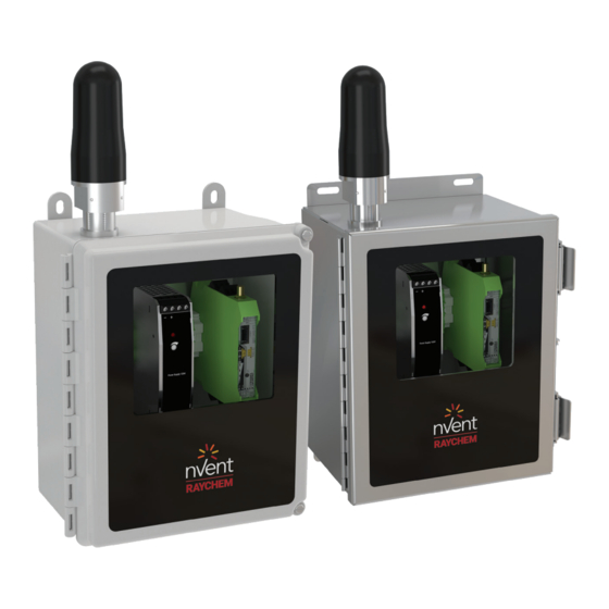
Summary of Contents for nVent RAYCHEM Elexant 9200i
- Page 1 Elexant 9200i Wireless Communications Interface nVent.com/RAYCHEM RAYCHEM-AR-H60819-Elexant9200i-EN-2009...
-
Page 2: Table Of Contents
TROUBLESHOOTING ..........................12 5.1 Troubleshooting Procedure......................12 APPENDIX A ............................13 LIST OF TABLES Table 1 - Elexant 9200i Enclosure Variants ....................4 Table 2 - Elexant 9200i Antenna Packages ....................5 LIST OF FIGURES Figure 1 - Elexant 9200i Assembly ......................7 Figure 2 - Input Power ..........................10 Figure 3 - RS-485 Connections ....................... -
Page 3: Overview
1. OVERVIEW This section contains an overview of the Elexant 9200i Wireless Communications product. It introduces the main features of the product, variations available, as well as provides directions on accessing manufacturer information that pertains to the equipment there-in. Introduction The nVent RAYCHEM Elexant 9200i is a Wireless Communications Interface that provides an alternative solution to hardwired Remote Monitoring and Configuration of Electric Heat Tracing Systems (EHT) systems. -
Page 4: Enclosure Variants
(See Notes 1 and 2) Catalog Number Part Number Description Elexant 9200i 868 MHz Phoenix Contact module in FG 10392-100 9200i-E-PC-868-FW enclosure with window, antenna, and pre-drilled holes for power (M25) and communications (M20) Elexant 9200i 868 MHz Phoenix Contact module in FG... -
Page 5: Antenna Package Variants
• Long distance coverage The Elexant 9200i is an encapsulation of a 3rd party transceiver and associated equipment. It provides a transparent communications bridge between a Master and Slave / Repeater transceiver, allowing for communications to span many kilometers. The main interface to a Heat Tracing Controller is a RS-485 Serial interface, supporting the Modbus RTU protocol.A full set of features can be found within the manufacturer’s... -
Page 6: Vital Information
Thermal representative. Operator Safety Considerations The Elexant 9200i Wireless Communications products are suitable for Class 1, Division 2, Groups A, B, C, and D hazardous areas (IECEx / ATEX Zone 2 approvals pending). Refer to RAYCHEM-IM-H60818-Elexant9200i-EN Installation Manual for more details. -
Page 7: Elexant 9200I Assembly
Elexant 9200i Assembly The figure below displays the different physical assemblies for the common Variants of the Elexant 9200i. Fiberglass Enclosure Fiberglass Enclosure Externally-mounted Antenna Connection Pre-mounted Antenna Stainless Steel Stainless Steel Externally-mounted Antenna Connection Pre-mounted Antenna Figure 1 - Elexant 9200i Assembly nVent.com/RAYCHEM... -
Page 8: Connection And Indicators
Connections and Indicators A. TB-1 Wiring Terminals Function Earth Ground (G) Power IN (L1) Power IN (N) B. TB-2 Wiring Terminals Function RS-485 + RS-485 – RS-485 Shield (SH) Note1 Earth Ground (G) Note 1: To provide isolated earth for comm shield, remove jumper between IE & PE. C. - Page 9 Connection with very good receive 2.0 to 2.5 V 2 Green LEDs are lit signal strength nVent RAYCHEM Elexant 9200i RM RSSI LED 1Y 2G 1W 1 Yellow LED and 1 Connection with good receive signal 1.5 to 2.0 V...
-
Page 10: Mounting And Removal Procedures
The ideal mounting method is to secure the enclosure to channel strut, or other structural components, using the included mounting hardware. Mounting and removal of the Elexant 9200i should only be attempted by trained personnel. If support is needed, contact nVent Technical Support (refer to section 1.3). -
Page 11: Load Connections
2.6.2 RS-485 Connections Wiring for RS-485 communications is made at screw terminals on Terminal Block TB-2. Figure 3 - RS-485 Connections 2.6.3 Antenna Coaxial Connection Depending on the package purchased, an external antenna may need to be connected. TNC (m) M20 Gland TNC (f) External... -
Page 12: Product Operations
3. PRODUCT OPERATIONS Programming and Configuration Please reference Phoenix Contact’s User Manual RAD-XXXX-IFS, or equivalent, for the latest information pertaining to this procedure. 4. FIRMWARE UPGRADE Firmware Upgrade Procedure Please reference Phoenix Contact’s User Manual RAD-XXXX-IFS, or equivalent, for the latest information pertaining to this procedure. - Page 13 APPENDIX A Specific Conditions of Safe Use The enclosure of the device shall be fitted with a locking mechanism such that it is only accessible with the use of a tool. To maintain an internal pollution degree 2 environment, after opening the enclosure, make sure there is no visible condensation or dust.
- Page 14 nVent.com/RAYCHEM RAYCHEM-AR-H60819-Elexant9200i-EN-2009...
- Page 15 nVent.com/RAYCHEM RAYCHEM-AR-H60819-Elexant9200i-EN-2009...
- Page 16 North America Europe, Middle East, Africa Asia Pacific Latin America Tel +1.800.545.6258 Tel +32.16.213.511 Tel +86.21.2412.1688 Tel +1.713.868.4800 Fax +1.800.527.5703 Fax +32.16.213.604 Fax +86.21.5426.3167 Fax +1.713.868.2333 thermal.info@nVent.com thermal.info@nVent.com cn.thermal.info@nVent.com thermal.info@nVent.com ©2020 nVent. All nVent marks and logos are owned or licensed by nVent Services GmbH or its affiliates. All other trademarks are the property of their respective owners. nVent reserves the right to change specifications without notice.

Need help?
Do you have a question about the Elexant 9200i and is the answer not in the manual?
Questions and answers