
Summary of Contents for BTR BDC Pro 400 24 V
- Page 1 Assembly and Commissioning Instructions BDC P according to Machinery Directive 2006 / 42 / EC (annex VI) BDC Pro (24 V DC / 230 V AC) - C hAin riVe for winDows...
- Page 2 ontents Abbreviations Target Groups Warning and Safety Symbols Intended Use 3 - 8 Safety Instructions Data sheet BDC Pro 24 V Data sheet BDC Pro 230 V Application areas and casement sizes Explanations on the product label 9 - 11 Inspection before the installation nstallatIon steP Installation prerequisite and Installation preparation...
-
Page 3: Target Group
reliminary emark BBreViatioNs arNiNg aND safety symBols iN these struCtioNs Index of abbreviations The symbols used in the instructions shall be strictly observed and have These abbreviations are used consistently throughout these assembly the following meaning: & operating instructions. Unless stated differently, all dimensions indi- cated in this document are in mm. - Page 4 The need for a risk assessment at the installation site The drive is in combination with an external Control Unit (e.g. from Btr) released for its proper use at a power- due to the reasonably foreseeable misuse. A risk assessment in accordance with the Machinery...
- Page 5 reliminary emark Hazard analysis according to DIN EN 60335-2-103 NSHEV according to NSHEV according to EN12101-2 with EN12101-2 without Use of the drive dual purpose for ventilation dual purpose for ventilation (1.Z.109) aUtIon Natural ventilation Keep people away during closing! Installation height of drive and lower edge of casement: >...
-
Page 6: Safety Instructions
afety nstruCtions afety iNstruCtioNs It is important to follow these instruc- Installation tions for the safety of persons. These These instructions address expert and safety-conscious arNiNg instructions shall be kept in a safe place electricians and / or qualifi ed personnel knowledgeable in for the entire service life of the products. - Page 7 afety nstruCtions Crush and shear points All-pole disconnecting devices shall be instal- To avoid injuries, crushing and shear points between led in the permanent electrical installation or casement and frame must be secured against entrapment external Control Unit for the drive. up to an installation height of 2,5 meters above the The mains supply lines 230 V / 400 V AC shall fl oor with appropriate measures.
-
Page 8: Ambient Conditions
afety nstruCtions Commissioning, operation and maintenance Replacement parts, fasteners and controls After the installation and after each modifi cation in the set The drive shall only be operated with control devices from up all functions shall be checked with a trial run. It shall the same manufacturer. -
Page 9: Data Sheet
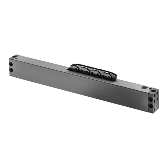
Order Data s [mm] L [mm] Version Finish PU / pcs. Part.-No. BDC Pro 400 24 V 10.300 E6 / C - 0 10.301 BDC Pro 600 24 V E6 / C - 0 10.302 BDC Pro 800 24 V... - Page 10 heet 230 V BDC P 230 V aC ata sheet ƒ Application: natural ventilation ƒ Internal intelligent control electronics ƒ Parallel connection up to 8 drives in one group ƒ High-quality stainless steel sidebow roller chain, without protruding rivet heads Options ƒ...
- Page 11 reParing ssembly (Casement size max. 4 m - depending on the system) PPliCatioN areas aND asemeNt sizes Bottom-hung casement und Top-hung casement Bottom-hung casement und Top-hung casement inward opening outward opening FAB min. = L + 100 mm FAB min. = L + 100 mm FAB >...
-
Page 12: I Nstallation Step
reParing ssembly 1: i nstallatIon steP NsPeCtioN Before the iNstallatioN Important instructions for a safe instal- Inspection of the intended use lation. Observe all instructions, wrong The planned use of the drive must be checked for com- arNiNg installation may result in serious injury! pliance with its intended use. -
Page 13: Scope Of Delivery
• Grains, • Grains BDC Pro ssembly nstructIon Part.-No. s (mm) L (mm) BDB 101 BDB 104 BDC Pro 400 24 V 10.300 bDc P BDC Pro 600 24 V 10.301 BDC P BDB 101 BDC Pro (24 V) 24 V... - Page 14 asement raCkets anD rame raCkets 3: B nstallatIon steP raCket imeNsioNs aND rill oles Dimensions and Drill holes Bracket-Set BDB 101 Bracket-Set BDB 104 (Part.-No.: 10.250) (Part.-No.: 10.350) Casement bracket Casement bracket ø5,5x9,5 M3x20 (SW 2,5) M3x25 (SW2,5) Frame bracket ø5,5 M5x10 (SW 4)
- Page 15 PPliCation xamPles PPliCatioN examPles Bottom-hung casement inward opening (Application examples) Rigid drive mounting directly on the window frame Bracket-Set BDB 101 (without frame bracket) BDC Pro BDB 101 reference edge Space on the frame = 28 mm Rigid drive mounting on the casement Bracket-Set BDB 104 BDB 104 BDC Pro...
- Page 16 ayout for raCket 4: h nstallatIon steP ole layout for raCket Bottom-hung casement inward opening Rigid drive mounting directly on the window frame - with Bracket-Set BDB 101 24 V Window versions: Bottom-hung - inward opening 230 V Top-hung - inward opening reference edge 24 V 1/2 FAB...
- Page 17 ounting BDB 101 nstallatIon steP igiD DriVe mouNtiNg with raCket Directly on the window frame - main closing edge or auxillary closing edge Inward opening windows „ Determine fastenings for drive BDC Pro „ Screw the Bracket-Set BDB 101 onto casement ...
- Page 18 ounting BDB 104 nstallatIon steP igiD DriVe mouNtiNg raCket On the casement - main closing edge or auxillary closing edge Inward opening windows „ Determine fastenings for Bracket-Set BDB 104 „ Attach drive BDC Pro to the frame brackets ...
-
Page 19: Cable Routing
able outing 6: C nstallatIon steP aBle routiNg Cable crossover without Cable crossover with Cable on casement Cable in glazing bead protective cable hose protective cable hose BDC Pro BDC Pro Cable duct glued on Drill hole in glazing bead protective (in addition secured with coun- (cable bushing protects against... - Page 20 leCtriC onneCtion 7: e nstallatIon steP leCtriC oNNeCtioN Make sure when establishing the connection Wire colour coding Direction of travel that there is no voltage at the terminals! Unused wires must be safely insulated! Colour DIN IEC 757 OPEN black CLOSE The running direction of the 24 V-drive may be changed brown...
- Page 21 Directive. Separate documents for performing a risk A = 1,42mm -> 1,5mm choosen assessment can be downloaded from the homepage of Firm Btr G (www.btr-hamburg.de). Laying and connecting the drive cable Operation of the power-operated window • Avoid extreme temperature differences in the instal- When operating the power-operated window safety lation area (danger of condensation).
- Page 22 It is recommended to conclude a maintenance contract. A sample main- • Drive run direction not • Check drive cables tenance contract can be downloaded from the homepage of correct Firm Btr G • Connecting cable not • Check all connection (www.btr-hamburg.de). connected...
-
Page 23: Warranty And Customer Service
• Wear and tear. Contact persons for possible warranty claims, for spare parts or accessories are the employees of the responsible branch offi ce or the responsible person at Firm Btr G Contact data are available at our homepage (www.btr-hamburg.de) iaBility We reserve the right to change or discontinue products at any time without prior notice. - Page 24 otiCe BDC Pro 24 V DC / 230 V DC AC...
- Page 25 otiCe BDC Pro 24 V DC / 230 V AC...
- Page 26 otiCe BDC Pro 24 V DC / 230 V DC AC...
- Page 27 Offenders will be held liable for the payment of damages. All rights reserved in the case of a patent award or utility model registration. Basically the General Terms and Conditions of Btr GmbH apply to all offers, supplies and services.
- Page 28 ♦ BTR GmbH ♦ ♦ Gemeindewald 11 ♦ D-86672 Thierhaupten ♦ ♦ Telefon: +49 8271 811 92-0 ♦ Fax: +49 8271 811 92-55 ♦ www.btr-hamburg.de 9000000251_V0.1_KW20/20...