
Summary of Contents for TOPMAQ MM3156
- Page 1 OWNER’S OPERATING MANUAL MM3156 DRUM SANDER CAUTION : READ THE INSTRUCTION MANUAL BEFORE USING APPLIANCE...
-
Page 2: Safety Alert Symbol
Technical data Model N o. MM3156 Max s anding w idth 560mm Max w orkpiece he ight 75mm Drum s peed 1440min Drum s ize 132X565mm Feed s peed 0-3m/min Dust por t di a meter 100mm Motor 230VAC,1500W Feed motor... -
Page 3: Rules For Safe Operation
CAUTION: Failure to obey safety warning may result in serious injury to yourself or to others. Always follow the safety precautions to reduce the risk of fire, electric shock, and personal injury. NOTE: Advise you of information or instructions vital to the operation or maintenance of the equipment. - Page 4 accidents. 4. DO NOT USE IN DANGEROUS ENVIRONMENTS. Do not use power tools near gasoline or other flammable liquids, in damp or wet locations, or expose them to rain. Keep the work area well lighted. 5. KEEP CHILDREN AWAY FROM POWER TOOLS. All visitors should be kept at a safe distance from the work area.
- Page 5 source. 22. STAY ALERT. Never operate a power tool when tired or while under the influence of drugs, alcohol, or medication. 23. MAKE SURE A TOOL IS CONNECTED only to the voltage marked on the nameplate. 24. NEVER USE A TOOL if its cover or any bolts are missing. If the cover or bolts have been removed, replace them prior to use.
-
Page 6: Grounding Instructions
12. DO NOT FORCE-FEED THE WORK PIECE through the machine. Let the sander apply the proper feed rate. 13. CHECK THE FEED BELT occasionally to make sure there is no debris or sawdust between any components. 14. SAND ONLY SOUND LUMBER; there should be no loose knots and as few tight knots as possible. -
Page 7: Extension Cords
EXTENSION CORDS When using a power tool at a considerable distance from a power source, use an extension cord heavy enough to carry the current that the tool will draw. An undersized extension cord will cause a drop in line voltage, resulting in a loss of power and overheating. - Page 8 can be removed in a single pass. DRUM SANDING ADVANTAGES One advantage of the wide drum sander is that you can work with material up to 405mm wide with this unit because of its open side design. Although you still abrasive sand with the grain, you do not have to read the grain to prevent tear-out.
-
Page 9: Loose Parts List
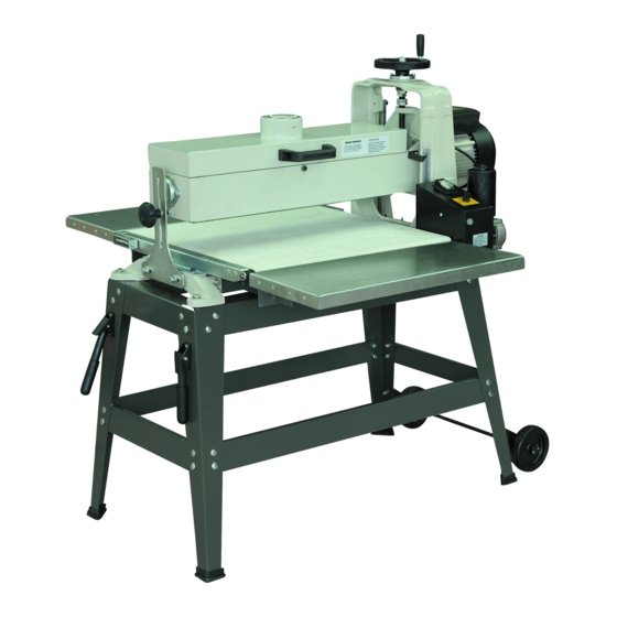
WOOD SPECIES TO BE CAUTIOUS WITH Highly resinous species will tend to quickly clog (load-up) abrasives and in many cases abrasive loading cannot be removed with belt cleaning sticks. The most notorious abrasive loaders are some common pine species. It is nearly impossible to clear the abrasive of the pitch, sap sawdust combination. - Page 10 Height Adjustment Handle Assembly Dust Collection Port Sanding Drum Elbow Drive Motor Sanding Drum Dust Cover Conveyor Feed Motor Conveyor Belt Variable Speed Tracking Adjuster Control Box Stand Mounting tafelverlenger Hole Support Stand with Easy Moving Handle and Wheel Figure 1 Sanding Drum Elevation...
- Page 11 6 mm Hex Wrench 4 mm Hex Wrech 10/12 mm Open End Wrench Height Adjustment Handle Height Adjustment Crank Figure 3 ASSEMBLY After unpacking your WDS (Wide Drum Sander) and checking the Loose Parts List for missing components, you are ready to assemble and install the Height Adjustment Handle Assembly.
- Page 12 Height Adjustment Shaft (with machined flat) Figure 5 3. Lower the Height Adjustment Handle Assembly onto the Height Adjustment Shaft and tighten the setscrew with the supplied 4mm Hex Wrench Key. (See Figure 7.) Height Adjustment Handle Assembly 11...
- Page 13 Figure 7 4. Secure the assembled Wide Drum Sander to the accessory workstand or to an adequately stable workbench or stand before operating the machine. WARNING: To prevent possible serious personal injury, always disconnect the Wide Drum Sander from the power source before servicing the unit or changing the abrasive strips.
-
Page 14: Drum Alignment
deflection are: 1. Excessive depth of cut. Decrease the depth of cut to minimize pressure on the sanding drum assembly. Refer to the Introduction to Drum Sanding section for hints regarding depth of cuts. (See Page10.) 2. Loose Elevation Tension Screws. Refer to Step 1 in the Drum Alignment section for hints regarding depth of cuts. - Page 15 Elevation Tension Adjustment screws Figure 9 2. To adjust the Elevation Tension Adjustment Screws, loosen the lock nuts, securing each screw in place. Loosen or tighten each screw, as required, in 1/4 turn increments to attain the desired fit and smoothness. Retighten the lock nuts to secure the tension screws in position.
- Page 16 Conveyor Table Drum Reference (Block of wood or leve) Note: Drum frame not depicted for clarity. Figure 10 If the measurement at A is greater than the same point at B by .020” or less, proceed as follows: 1. Loosen the 2 outboard conveyor table mounting bolts as shown in Figure 15...
- Page 17 Conveyor Table Mounting Bolts Figure 11 2. Slide one or both of the shims (not supplied) as needed under the edge of the conveyor table as shown. 3. Tighten conveyor table mounting bolts. Re-check the measurement at A and at B. Sand a piece of wood and check for uniform thickness.
- Page 18 Inboard Conveyor Inboard Conveyor Table Alignment Table Bolts. Alignment Bolts. Front Rear Figure 12 NOTE: If the unit is bolted to a stand or bench, loosen the mounting bolts at the motor end. 2. Using the Height Adjustment Handle Assembly, lower the drum until the distances at A and B are equal.
-
Page 19: Helpful Hint
3. If the conveyor feed belt is tracking towards the inboard (motor side) of the machine, tighten (add tension) to the tracking adjustment screw on that side of the machine. NOTE: Due to the width of the conveyor feed belt, tracking adjustments may not become apparent immediately! Increase the speed of the conveyor feed belt to hasten the effects of your adjustments. - Page 20 considered when determining the amount of material to be removed on each pass. Never remove more than 0.8mm of material in one pass. The variable feed rate is set to prevent burning and provide a smooth sanded surface on different types and widths of materials. As a general rule, 1/4 turn or 0.4mm or less is recommended stock removal for coarser grits and softer woods, while 1/8 of a turn or 0.2mm may be more desirable with harder woods and/or finer grits if abrasives.
- Page 21 INSTALLING NEW REPLACEMENT ABRASIVE STRIPS WARNING: To prevent possible serious personal injury, always disconnect the Wide Drum Sander from the power source before serving the unit or changing the abrasive strips. Abrasive strips are available from local dealer in precut strips which require no special measuring or trimming before installation.
- Page 22 hand and guiding the material onto the drum. Use this technique to warp the abrasive strip edge to edge radially around the drum. Make sure you do not overlap the material as you wrap the abrasive (Figure 16). The material should be flush to slightly gapped, but not overlapped, during the wrap.
- Page 23 NOTE: In some cases, if the abrasive strip stretches, it may be necessary readjust/reposition the abrasive clip points on the abrasive strip. Ensure the tension remains positive on the abrasive strip during extended use. ABRASIVE GRIT SELECTION THE SANDING PROCESS Smoothing wood, or sanding, is the process of making finer and finer scratches until they become so small they are no longer visible to the human eye.
-
Page 24: Maintenance Of Unit
MAINTENANCE OF UNIT WARNING: To prevent possible serious personal injury, always disconnect the Wide Drum Sander from the power source before serving the unit or changing abrasive strips. Keep your Wide Drum Sander clean. Remove accumulated sawdust from the drum and other working parts. Frequently clean resin buildup from the inner drum using a kerosene or a resin remover dampened cloth with the unit disconnected from the power source. - Page 25 and the abrasive strip must be replaced. 1. Heed all warnings and use extreme caution when performing this cleaning operation. 2. Set the conveyor belt speed control knob to lowest feed setting. Avoid contact with conveyor feed belt. 3. Open the protective dust cover to expose the sanding drum and abrasive strip.
- Page 26 4. Using the supplied 6 mm wrench key, remove both conveyor table mounting bolts on the outboard open side of the wide drum sander (See Figure in the Drum Alignment section for reference.) 5. Reduce tension on the conveyor feed belt by rotating both the inboard and outboard conveyor feed...
- Page 27 DIAGRAM 1 26...
- Page 28 DIAGRAM 1 PARTS LIST: Handle Sleeve Handle Screw M4 X 35 Support Base Fixing Base Screw M6 X 10 Hex nut M4 Front Stand(left) Front Stand(right) Front stand(right) Hex Nut M6 Short Cross Stand Short Support Plate(left) Long Cross Stand Long Support Plate(right) Long Support Plate(right ) Hex Nut M8...
- Page 29 DIAGRAM 2 28...
- Page 30 DIAGRAM 2 PARTS LIST: DESCRIPTION Side worktable ass. Screw M8X20 Protective cover 6 5 Locking nut M8 1 6 Big washer 1 7 Handle 2 8 Screw M8×25 1 9 Screw M4×8 1 Clamp 1 Spring washer 4 1 Nut M4 Drum roller 1...
- Page 31 2 Fixing base 2 Left active block 2 Right active block 4 Locking nut M4 8 Cover 2 Fasten bar 1 Nut M12 1 Flat washer12 Label Handle ass. Lifting shaft 4 Bolt M5×16 Waning plate 23 Ball 1 Plate 1...
- Page 32 Screw M5X16 Spring Nut M5 Feed belt Out feed roller ScrewM8X12 Worktable accessory Support block Bolt M6X16 Flat washer6 Spring washer6 Infeed roller Screw M5X20 Switch box housing Commutate block Connector ScrewM5X10 Soleplate Transformer Screw M4X10 Bolt M6X20 Bolt Connecting board Switch Resistance board Cable holder...
Need help?
Do you have a question about the MM3156 and is the answer not in the manual?
Questions and answers