Table of Contents
Advertisement
Quick Links
VLC5501
Immobiliser installation manual
Installation manual - Version 2.4
__________________________________
__
Attention!!!
Installation of this security product is additional protection for your vehicle, but it
does not protect your vehicle from all possible thefts.
VLC5501 Vapormatic Immobiliser Installation Manual
1 of 21
Advertisement
Table of Contents

Subscribe to Our Youtube Channel
Related Manuals for Vapormatic VLC5501

Summary of Contents for Vapormatic VLC5501
- Page 1 Immobiliser installation manual Installation manual - Version 2.4 __________________________________ Attention!!! Installation of this security product is additional protection for your vehicle, but it does not protect your vehicle from all possible thefts. VLC5501 Vapormatic Immobiliser Installation Manual 1 of 21...
- Page 2 VLC5501 Vapormatic Immobiliser Installation Manual 2 of 21...
-
Page 3: Table Of Contents
Testing the system: ...................... 13 Fault Finding Chart: ......................14 Technical parameters: ......................16 Keypad module:......................16 Blocking modules: ....................... 16 Keypad Override Disc:....................16 Additional relays: ......................16 Conditions of sale: ....................... 17 VLC5501 Vapormatic Immobiliser Installation Manual 3 of 21... -
Page 4: Product Warranty And Registration
Product warranty and registration: Warranty of this product is for 12 months. If you register this product on line, Vapormatic will give a further 12 months warranty free, giving 24 months in total. To register this product please go to: www.vapormatic.com/vehiclesecurity. -
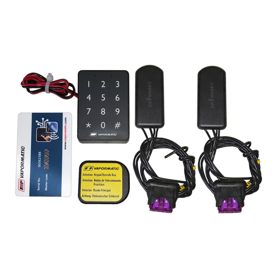
Page 5: Kit Contents
4. Immobiliser blockers x 2 10. 3 Amp fuses x 3 5. Keypad Override Disc 11. PIN card with unique code (no image) 6. Keypad Override Disc battery 12. Installation CD (no image) VLC5501 Vapormatic Immobiliser Installation Manual 5 of 21... -
Page 6: Wiring Suggestions
NOTE: Care must be taken not to induce any vehicle diagnostic error codes of any kind whilst interrupting power supply to CAN bus devices on modern vehicles. VLC5501 Vapormatic Immobiliser Installation Manual 6 of 21... -
Page 7: Immobiliser Blocker Module Wiring Diagrams
For this reason DO NOT leave the vehicle unattended whilst the Keypad Override Disc is within a 5 metre range. Damaged keypads or lost discs can be ordered from Vapormatic, quoting the serial number printed on all components of this system. -
Page 8: Immobiliser Blocker Module Wiring Diagram Without Relays
8 Volts, the blockers will drop out causing the vehicle not to start. Fuse Holders: The Fuse holders supplied are of a special automotive anti-vibration type, therefore each fuse is held tighter than normal. VLC5501 Vapormatic Immobiliser Installation Manual 8 of 21... -
Page 9: Immobiliser Blocker Module Wiring Diagram With Relays
8 volts when the engine is cranking. Some ignition circuits are not live when the ignition key is in the start position, if the voltage decays below 8 Volts, the blockers will drop out causing the vehicle not to start. VLC5501 Vapormatic Immobiliser Installation Manual 9 of 21... -
Page 10: Keypad Installation
Keypad installation: Mounting of the Keypad module: The Vapormatic keypad module transmits an authorisation code to the two immobiliser blockers wirelessly, unblocking the electrical system and allowing the vehicle to start. The keypad module must be installed in a dry location normally inside the vehicles cabin providing easy access to the keypad buttons. -
Page 11: Keypad Wiring Diagram
Keypad wiring diagram: The Vapormatic keypad only requires an ignition live and a good chassis earth, all other communications to the immobiliser blocker modules are wireless. Earth wire (-): Must be firmly secured to the vehicle’s chasses. Power wire (+): Must be connected to an ignition live 8V to 16V, (Ignition live is 0 volts with the ignition switched off, and 8 to 16 volts with the ignition switched on) using one of the three in-line fuse holders supplied. -
Page 12: Keypad Override Disc
With the battery correctly inserted, the red LED on the printed circuit board will flash twice. Carefully place the combined circuit board and battery into enclosure 1, and snap enclosure 2 into place. VLC5501 Vapormatic Immobiliser Installation Manual 12 of 21... -
Page 13: Testing The System
5. Wait until you hear a double beep emitted from the keypad and the green LED switches ON. (This should be within a couple of seconds) 6. Try to start the engine. If the engine can be started, this test has been successfully finished. VLC5501 Vapormatic Immobiliser Installation Manual 13 of 21... -
Page 14: Fault Finding Chart
Is Keypad with-in a 5 metre range of the immobiliser blockers Check the serial numbers match on both the immobiliser blockers (sticker on outer casing), and Keypad mounting plate (Sticker on mounting plate) VLC5501 Vapormatic Immobiliser Installation Manual 14 of 21... - Page 15 Disc (Sticker on PCB board) Check for correct code, enter factory reset 8 digit code (please refer to the PIN code card section in the User manual) Complete installation tests as per manual VLC5501 Vapormatic Immobiliser Installation Manual 15 of 21...
-
Page 16: Technical Parameters
Value Operating frequency 2,4GHz Operating range 5 metres Battery type CR2430 Battery life 12 months Operating temperature -30..+85 C Dimensions 49x41x6 mm Additional relays: Parameter name Value Operating voltage Maximal current draw VLC5501 Vapormatic Immobiliser Installation Manual 16 of 21... -
Page 17: Conditions Of Sale
Conditions of sale: This product is subject to an extended warranty – please see www.vapormatic.com/vehiclesecurity. Please note: The terms and conditions of sale currently in effect are always those as shown on our website at www.Vapormatic.com. 1. General (i) All orders are accepted by the Company from the Buyer on the following terms, conditions and exceptions and no other terms, conditions or warranties shall apply unless agreed to in writing by the Company. - Page 18 (whether or not the goods are delivered in instalments and some have been paid for by the Buyer) and until such time the Buyer shall hold the goods in a fiduciary capacity for the Company and in particular the Buyer: VLC5501 Vapormatic Immobiliser Installation Manual 18 of 21...
- Page 19 (e) The provisions of this Clause 4(v) shall survive the termination of the contract for whatever reason and in particular but without limitation termination of the contract by the Company by the acceptance of any repudiation of the contract by the Buyer. 5. Delay and Force Majeure VLC5501 Vapormatic Immobiliser Installation Manual 19 of 21...
- Page 20 The Buyer will, at the request of the Company, return such defective goods to the Company carriage paid. (iii) The Company shall be under no liability under the above warranty: VLC5501 Vapormatic Immobiliser Installation Manual 20 of 21...
- Page 21 (c) where the goods are transported to the Buyer at the Buyer's risk and the defect occurred during transit; (d) in respect of non-Vapormatic branded goods. In that case the buyer shall only be entitled to the benefit of any such warranty or guarantee as is given by the manufacturer to the Company.
Need help?
Do you have a question about the VLC5501 and is the answer not in the manual?
Questions and answers