Table of Contents
Advertisement
Quick Links
MOTION DETECTOR KIT
MODEL AK-510
Assembly and Instruction Manual
Elenco
®
Electronics, Inc.
Copyright © 2006, 1994 by Elenco
®
Electronics, Inc. All rights reserved.
Revised 2006
REV-N
753010
No part of this book shall be reproduced by any means; electronic, photocopying, or otherwise without written permission from the publisher.
Advertisement
Table of Contents

Subscribe to Our Youtube Channel
Related Manuals for Elenco Electronics AK-510


Summary of Contents for Elenco Electronics AK-510
- Page 1 MOTION DETECTOR KIT MODEL AK-510 Assembly and Instruction Manual Elenco ® Electronics, Inc. Copyright © 2006, 1994 by Elenco ® Electronics, Inc. All rights reserved. Revised 2006 REV-N 753010 No part of this book shall be reproduced by any means; electronic, photocopying, or otherwise without written permission from the publisher.
-
Page 2: Parts List
PARTS LIST If you are a student, and any parts are missing or damaged, please see instructor or bookstore. If you purchased this kit from a distributor, catalog, etc., please contact Elenco mail is at the back of this manual) for additional assistance, if needed. DO NOT contact your place of purchase as they will not be able to help you. - Page 3 IDENTIFYING RESISTOR VALUES Use the following information as a guide in properly identifying the value of resistors. BAND 1 1st Digit Color Digit Black Brown Orange Yellow Green Blue Violet Gray White IDENTIFYING CAPACITOR VALUES Capacitors will be identified by their capacitance value in pF (picofarads), nF (nanofarads), or µF (microfarads). Most capacitors will have their actual value printed on them.
- Page 4 CONSTRUCTION Introduction The most important factor in assembling your AK-510 Motion Detector Kit is good soldering techniques. Using the proper soldering iron is of prime importance. A small pencil type soldering iron of 25 - 40 watts is recommended. The tip of the iron must be kept clean at all times and well tinned.
- Page 5 INTRODUCTION The AK-510 is an infrared motion detector kit. The objective of the kit is to teach the operations of the four sections that make up the kit. The four sections are shown in the block diagram below. OPERATIONAL POWER...
-
Page 6: Infrared Detector
When the crystal temperature changes, a voltage is produced at the electrodes of the crystal element. This type of crystal is used in this motion detector kit inside the infrared (IR) detector. INTERNAL DESIGN... -
Page 7: Field Of View
This causes a change in current from the drain to source. Very little power is required at the gate to control the larger current flow from source to drain. The benefits of this type of detector are low radio interference, low noise, specially suited response. The IR detector is sealed in a metal housing to prevent electromagnetic interference and to keep them clean. -
Page 8: Low Pass Filter
NEGATIVE FEEDBACK The open loop gain (or maximum gain) of a typical op- amp is very high (usually greater than 100,000), enabling a very small input voltage to drive the op- amp output to it’s extremes. resistor is connected between the output and inverting input terminals allowing a portion of the output signal to be brought back and cancel part of the input (Figure 8). -
Page 9: Band Pass Filter
BAND PASS FILTER The combination of a low and high pass filter create what is called a Band Pass Filter. The frequencies passed by each filter overlap and create a bandwidth (range), passing all signals within the bandwidth and reducing all others. Figure 13 illustrates the general band-pass response curve. - Page 10 ASSEMBLE COMPONENTS TO THE PC BOARD R2 - 47kΩ 5% 1/4W Resistor (yellow-violet-orange-gold) C2 - 10µF 25V Electrolytic (see Figure D) C4 - 22µF 25V Electrolytic (see Figure D) R5 - 39kΩ 5% 1/4W Resistor (orange-white-orange-gold) R3 - 75kΩ 5% 1/4W Resistor (violet-green-orange-gold) C8 - 500pF (501) Discap D1 - 1N4148 Diode...
- Page 11 ASSEMBLE COMPONENTS (CONTINUED) – Inside Pads Outside Pads B1 - Battery Snap Identify the battery snap B1. Insert the red and black wires through the hole from the copper side of the PC board. Insert the red wire into the (+) positive hole and the black wire into the (–) negative hole as shown above.
-
Page 12: Final Assembly
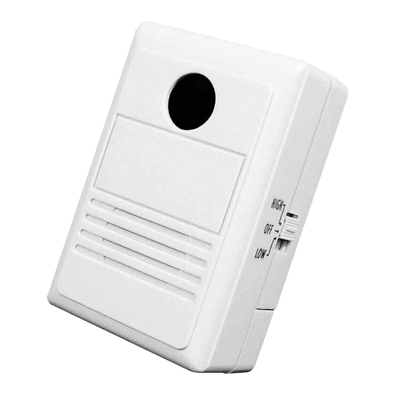
FINAL ASSEMBLY Step 1 Place the speaker into the front case as shown in Figure 16. Use two #4 x 1/4” screws and two #4 washers to secure it into place. Step 2 Push the switch key onto the switch as shown in Figure 17. -
Page 13: Installation
Step 4 Attach a 9V battery to the battery snap and place it into the case. Snap the battery cover into the back case as shown in Figure 19. Step 5 Place the unit onto a table and turn it on. Move to one side of the detector so that you are out of the field of view of the detector. -
Page 14: Troubleshooting Guide
TROUBLESHOOTING GUIDE The values given below are approximate. POWER SUPPLY 1. Measure the voltage at IC3. Pin 3 = 9V, Pin 1 = 4.75 - 5.25V A. Check soldering around IC3 and C6. B. Check for short to GND from pins 2 and 3. C. - Page 15 4. Measure the voltages at IC1 when activated. A. Incorrect voltage readings: 1. Check resistors R3 - R12 for correct value. 2. Check diode D1 polarity. 3. Check C3 and C4 polarity. 4. IC1 may be defective. SOUND GENERATOR Measure the voltage at the following pins on U2, as listed in the chart below. A.
- Page 16 QUIZ 1. The 9V battery supplies a . . . A. positive AC voltage. B. DC voltage. C. AC voltage. D. rectified DC voltage. 2. A human’s maximum thermal radiation is between . . . A. 3 and 5µm. B. 9 and 13µm. C.
-
Page 17: Schematic Diagram
SCHEMATIC DIAGRAM -16-... -
Page 18: Specifications
SPECIFICATIONS Power • 9V DC battery Current • Operating 60mA (average) • Standby Typical less than 4mA Detection • Pyroelectric Infrared Sensor. GLOSSARY OF TERMS Amplify To enlarge or increase. Amplitude The greatest difference above a reference, usually zero. Analogy Likeness or resemblance in relations of different objects. - Page 19 Low Pass Filter Decreases all signals above a certain frequency and passes frequencies below that frequency. Negative Feedback To allow a portion of the output signal to be brought back and cancel part of the input. Noise A random, persistent disturbance of a signal. Open Loop Gain The maximum gain available without feedback.
- Page 20 Elenco ® Electronics, Inc. 150 Carpenter Avenue Wheeling, IL 60090 (847) 541-3800 Web site: www.elenco.com e-mail: elenco@elenco.com...
Need help?
Do you have a question about the AK-510 and is the answer not in the manual?
Questions and answers