Table of Contents
Advertisement
Quick Links
Advertisement
Table of Contents

Subscribe to Our Youtube Channel
Related Manuals for ASTEK A33606-PCI-60-6A SAS-2

Summary of Contents for ASTEK A33606-PCI-60-6A SAS-2
- Page 1 A33606-PCI-60-6A SAS-2 Expander User Manual Version: A...
- Page 2 A33606-PCI-60-6A SAS-2 Expander User Manual CHANGE SHEET DATE DESCRIPTION OF CHANGE Preliminary Copy 1/15/14 Initial Release Correct GPIO’s nomenclature and sinking current for diode. 1/13/14 1/28/14 Updated Crypto Erase Function and pin descriptions Copyright © 2014 by Astek Corporation. All rights reserved Ver. A...
- Page 4 Astek; nor does the purchase or use of a product from Astek convey a license under any patent rights, copyrights, trademark rights, or any other of the intellectual property rights of Astek or third parties.
-
Page 6: Table Of Contents
5 Crypto Erase Function ........................22 6 Specifications ............................25 Electrical Specifications ............................25 Environmental Specifications ..........................25 Mechanical Specifications ............................25 7 Troubleshooting ........................... 27 Diagnostics ................................27 Support ................................... 27 Copyright © 2014 by Astek Corporation. All rights reserved Ver. A... -
Page 7: Introduction
5.25” shell for mounting in a 5.25” bay on a traditional PC chassis. The Astek expander SAS interface is compatible with the ANSI Serial Attached SCSI Specification, revision 2.0 and the Serial ATA Specification, revision 2.6. The functionality of the expander board comes from the LSISAS2X36 expander chip. -
Page 8: Installation Procedures
For external connection, connect the host to J2 using an SFF-8088 cable. Step 5. Attach drives to the expander card. The mapping of drive number to connector is shown below. Copyright © 2014 by Astek Corporation. All rights reserved Ver. A... -
Page 9: Software Installation
HBA/RAID card contain the necessary support for expanders in the system. Follow the recommended instructions for creating RAID arrays and disk arrays for the HBA or RAID card manufacturer. Ver. A Copyright © 2014 by Astek Corporation. All rights reserved... -
Page 10: Typical Use Cases
Host port on the 2 expander. Additional drives can be added to the SAS topology by adding more expanders to the system in the same manner. Copyright © 2014 by Astek Corporation. All rights reserved Ver. A... - Page 11 Installation Procedures A33606-PCI-60-6A Card HBA / RAID Card A33606-PCI-60-6A Card Ver. A Copyright © 2014 by Astek Corporation. All rights reserved...
-
Page 12: A33606-Pci-60-6A Characteristics
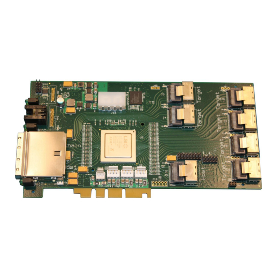
The A33606-PCI-60-6A board outline is shown below. Key interfaces are highlighted. Heartbeat LED Input Power Front Panel LEDs RJ-11 Serial Port Internal iPass (SFF-8087) SAS LEDs External iPass (SFF-8088) SAS LEDs Enclosure Services Header Temp Sensor Expander Connectors Copyright © 2014 by Astek Corporation. All rights reserved Ver. A... -
Page 13: Serial Port (Rj-11)
DB9 Pin A33606-AIC-01 Ground A compatible adapter for use with this interface is an Astek Corporation A40100-CBL-03. Other cables may be utilized as long as they conform to the above pinout. Heartbeat LED When the system is powered on and the expander chip is functioning properly, the Heartbeat LED, D9, will blink continuously. -
Page 14: Sas Leds
The system is OK. an enclosure fault. Input Power The A33606-PCI-60-6A requires 12V power through a standard 4-pin HDD connector. The table below shows the pinout of the power connector. Copyright © 2014 by Astek Corporation. All rights reserved Ver. A... -
Page 15: Internal Ipass (Sff-8087)
Each SFF-8087 includes Serial GPIO control for 4 drives. SGPIO is utilized to drive LEDs on a backplane board. The A33606-PCI-60-6A conforms to the requirements in the SFF-8485 Specification for Serial GPIO (SGPIO) Bus. Connector utilization is shown below Ver. A Copyright © 2014 by Astek Corporation. All rights reserved... -
Page 16: Enclosure Services Header
The Enclosure Services Header provides connectivity for GPIO-type enclosure services on J34. Additional information on SCSI Enclosure Services is located in the Other Connectors Other connectors not listed above are reserved for Astek use or for future use. SCSI Enclosure Services (SES) Section. Signal Name... -
Page 17: Temperature Sensor Header
GPIO1 and GPIO4 can be utilized for additional enclosure service I/O such as intrusion detection, additional LEDs, alarm, door lock, etc. Default firmware does not utilize these signals. Contact Astek with your requirements to obtain a customized configuration to utilize these pins. - Page 18 PWM / Speed Control The fans can be monitored and controlled through SCSI Enclosure Services (SES). Additional information on SES is located in the SCSI Enclosure Services (SES) Section. Copyright © 2014 by Astek Corporation. All rights reserved Ver. A...
-
Page 19: Front Panel
J2: Status LEDs: - Bottom/Left: Yellow Fault LED - Top/Right Green Activity LED Other Connectors Other connectors not listed above are reserved for Astek use or for future use. Ver. A Copyright © 2014 by Astek Corporation. All rights reserved... -
Page 20: Scsi Enclosure Services (Ses)
Thresholds for high and low voltage limits can be set through SES. If a voltage threshold limit is exceeded, the expander will report a failure through SES and illuminate the ERROR LED on the front panel. The default thresholds are listed below. Copyright © 2014 by Astek Corporation. All rights reserved Ver. A... -
Page 21: Cooling Elements
The expander element contains information about the A33606-PCI-60-6A product such as product name, revision, firmware version, etc. Customization Many of the SES settings and data can be customized to the application needs. Contact Astek to obtain a customized expander configuration to make your product stand out from the crowd. Ver. A... -
Page 22: Crypto Erase Function
Crypto Erase Completed with an FAST-BLINK ½ Hz, 50% Duty Cycle of GPIO3 error condition. transitioning between ON and No Crypto Erase function in GPIO3 is Tri-Stated continously progress. Copyright © 2014 by Astek Corporation. All rights reserved Ver. A... - Page 23 Failed (progress (Block SENSE Done? does not change) Erase) Block Erase Service Action • Command 0x48 per SBC-3, Section Successful • 5.24.2.3 Implemented per SBC-3, Section 4.11 • Latch LED Ver. A Copyright © 2014 by Astek Corporation. All rights reserved...
- Page 24 VIN = 0V +/- 1 Electrical Characteristics of GPIO3, Open-Drain Output Pin Parameter Conditions Unit Max Voltages Current Sink, IOL Output Low Voltage, VOL IOL=-6mA High Level Output VOUT=3.3V Current, IOH Copyright © 2014 by Astek Corporation. All rights reserved Ver. A...
-
Page 25: Specifications
Number of SAS/SATA ports: SFF-8087 Connectors: 7 w/ universal keying and SGPIO support SFF-8088 Connectors: * 5V and 18V configurations are available with certain limitations. Contact Astek for specific details. Environmental Specifications Operating Conditions Temperature: 0 °C to +55 °C ... - Page 26 The A33606-PCI-60-6A does not utilize signals or power from the PCI, PCI-X, or PCIe bus. The PCI socket provides a mechanical location to store the A33606-PCI-60-6A in a chassis. The card should be installed in a system by following the system manufacturer’s recommended procedures. Copyright © 2014 by Astek Corporation. All rights reserved Ver. A...
-
Page 27: Troubleshooting
Support For additional support, contact your Product Manager or email support@astekcorp.com. Astek can be contacted at (719) 260-1625 or toll-free at (800) 850-9055. Ver. A Copyright © 2014 by Astek Corporation. All rights reserved...
Need help?
Do you have a question about the A33606-PCI-60-6A SAS-2 and is the answer not in the manual?
Questions and answers