Table of Contents
Advertisement
Quick Links
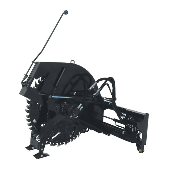
Heavy Duty Rock Saw
Some dust created by power sanding, sawing, grinding, drilling, and other
construction activities contains chemicals known to the State of California to cause cancer, birth
defects or other reproductive harm. Some examples of these chemicals are:
Lead from lead based paints,
Crystalline silica from bricks and cement and other masonry products, and
Arsenic and chromium from chemically treated lumber.
Your risk from these exposures varies, depending on how often you do this type of work. To reduce
your exposure to these chemicals: work in a well ventilated area, and work with approved safety
equipment, such as those dust masks that are specially designed to filter out microscopic particles.
18HDRS & 24HDRS
Skid Steer Loaders
Read this manual before use.
For
Operator's Manual
Maintenance and
Parts Information
Advertisement
Table of Contents

Subscribe to Our Youtube Channel
Summary of Contents for Erskine Attachments 18HDRS
- Page 1 Heavy Duty Rock Saw 18HDRS & 24HDRS Skid Steer Loaders Operator’s Manual Maintenance and Parts Information Read this manual before use. Some dust created by power sanding, sawing, grinding, drilling, and other construction activities contains chemicals known to the State of California to cause cancer, birth defects or other reproductive harm.
-
Page 2: Table Of Contents
Serial Number………….. YOUR ATTACHMENTS DEALER ADDRESS: PHONE: CONTACT: NOTE: Erskine Attachments LLC reserves the right to make improvements in design or changes in specifications at any time without notice and without incurring any obligations to install them on units previously sold. -
Page 3: Safety
Indicates potentially Erskine Attachments LLC cannot anticipate every hazardous situation which, if not avoided, possible circumstance that might involve potential will result in death or serious injury. hazard. The safety messages found in this manual ... - Page 4 Avoid High Pressure Fluids Hazard Do not modify equipment or add attachments that Escaping fluid under pressure can are not approved by Erskine Attachments LLC. penetrate the skin causing serious injury. Use adequate safety warning lights and devices as ...
-
Page 5: Serial Number/Decal Location
(identification made by serial number) may use different parts, or it may be necessary to use different procedures in doing a specific operation. Serial number plate is located on the upper right side step. Part Number: Model Decal 319455 – 18HDRS 319456 – 24HDRS Location: Each side of rotor w/a... - Page 6 Part Number: 318968 (18”) 318969 (24”) Safety Decals Locations: Location: On depth tube The locations of the safety decals are shown. If these Quantity: decals are missing, damaged, or painted over they must be replaced. Call Erskine Attachments LLC (218-435-4045) for replacement decals.
-
Page 7: Mounting Instructions
MOUNTING INSTRUCTIONS After uncrating the attachment, use the following procedure to mount the Heavy Duty Rock Saw to the loader. WARNING! Coupler wedges or pins must extend through the holes in the attachment mounting plate. Levers must be fully down and locked. Failure to secure wedges or pins can allow attachment to come off and cause injury or death. - Page 8 MOUNTING INSTRUCTIONS 8. Connect the hydraulic quick couplers from the attachment to the loader. IMPORTANT: Make sure the quick couplers are fully engaged. If the quick couplers do not fully engage, check to see that the couplers are the same size and brand. Do not force the quick couplers together.
-
Page 9: Operating Instructions
NOTE: The depth should be read at the top edge of the white indicator. (Depth of cut ranges from 0 to 18 inches on the 18HDRS and 0 to 24 inches on the 24HDRS.) 7. Disengage the auxiliary hydraulic oil flow and reduce the engine speed to low idle. - Page 10 OPERATING INSTRUCTIONS Operation To avoid injury or death from tipover, never use attachment on an incline. To avoid injury or death, carry attachment as low as possible. NOTE: If using the guide roller be sure to place it onto the ground prior to climbing in the skid steer. 1.
-
Page 11: Routine Maintenance
ROUTINE MAINTENANCE WARNING: Lower the rock saw to rest on the skid shoes and rollers, shut down the engine, relieve the hydraulic pressure to the attachment, wait for all motion to stop, and set park brake before leaving the operator’s seat to perform service of any kind. It is the operator’s responsibility to make daily inspections of the attachment and loader for damage, loose bolts, fluid leaks, or anything else that could cause a potential service or safety problem. - Page 12 ROUTINE MAINTENANCE Pick Inspection, Setup, Removal, & Installation Inspection: The factory installed carbide picks are specifically designed to be a wear product. The life expectancy Replace of the picks will depend greatly on the hardness, the abrasiveness, and the thickness of the material being cut.
- Page 13 ROUTINE MAINTENANCE Always wear eye protection that meets ANSI Z87.1 when removing and installing picks. Removal: IMPORTANT: The use of an improper tool to remove or install the picks may cause damage to the picks or pick holders. Always pick installation/removal tool provided with the rock saw.
- Page 14 ROUTINE MAINTENANCE GEARBOX MAINTENANCE The first gearbox oil change must be done between the first 15 – 20 hours of use. Subsequent gearbox oil changes should occur between 800 – 1000 hours of use or annually whichever comes first. IMPORTANT: Fluids such as engine oil, gear lube, and hydraulic fluid must be disposed of in an environmentally safe manner.
- Page 15 ROUTINE MAINTENANCE Rock Saw Gearbox Oil Replacement (continued) 11. Attach the chain hook of the 1 ton hoist to the front lift point and lift slightly so the cutter head rotates freely. ”) socket through the 12. Insert the 30mm (1 circular cutout and over the 20mm lug nut.
- Page 16 ROUTINE MAINTENANCE Rock Saw Gearbox Oil Replacement (continued) 25. Use an approved oil drain pan and place it below the gearbox. 26. Remove the drain plug located on the bottom of ”) Allen wrench. the gearbox with the 8mm ( 27.
- Page 17 ROUTINE MAINTENANCE Rock Saw Gearbox Oil Replacement (continued) 40. Move around to the right hand side of the saw. 41. Push the cutter head back onto the motor flange and lift the saw slightly so the cutter head is supported by the wheel studs. 42.
-
Page 18: Parts Information
PARTS INFORMATION ITEM PART NO. DESCRIPTION STOCK NO. 318925 ARM DEPTH R-SAW HD LH 18 W/A 318927 ARM DEPTH R-SAW HD LH 24 W/A 318911 ARM GUIDE ROD R-SAW HD W/A 319311 SKID SHOE ROCK SAW W/A 319328 BUSH 3 X 1.27 X 1.5 Z 318988 PUSH ROD DEPTH GAUGE 18 W/A Z 318980... - Page 19 PARTS INFORMATION...
- Page 20 PARTS INFORMATION ___________________ ITEM PART NO. DESCRIPTION STOCK NO. 318920 MOUNT FRAME R-SAW HD W/A 318922 FRAME SHIELD R-SAW HD 18 W/A 318923 FRAME SHIELD R-SAW HD 24 W/A 318924 ARM DEPTH R-SAW HD RH 18 W/A 318926 ARM DEPTH R-SAW HD RH 24 W/A 318957 BACKING PLATE 26 R-SAW PNTD 319311...
- Page 21 PARTS INFORMATION...
- Page 22 ROTOR BLADE WHEEL 2.75 X 48 W/A 319499 ROTOR BLADE WHEEL 2.5 X 60 W/A 318921 MOUNT BEARING R-SAW HD W/A 314830 TOOTH BULLET CP/RS CONCRETE 18HDRS REPLACEMENT PKG 318693 314830 TOOTH BULLET CP/RS CONCRETE 24HDRS REPLACEMENT PKG 318694 318970 MOTOR ASSM 313568...
- Page 23 PARTS INFORMATION...
- Page 24 PARTS INFORMATION ___________________ ITEM PART NO. DESCRIPTION STOCK NO. 318986 KIT HOSE ROCK SAW HD 18 318987 KIT HOSE ROCK SAW HD 24 312138 HOSE 3/8 X 38 6FJX-6FJX90 PORT B TO CYL ROD 319384 HOSE 3/8 X 20 6FJX-6FJX90 PORT A TO CYL BASE 319475 VALVE ASSM ROCK SAW 2 FUNC-2...
- Page 25 PARTS INFORMATION ITEM PART NO. DESCRIPTION STOCK NO. 318986 KIT HOSE ROCK SAW HD 18 318987 KIT HOSE ROCK SAW HD 24 313489 HOSE 3/8 X 54 6FJX-6FJX90 BASE TO B, RODS TO A 312136 HOSE 3/8 X 32 6FJX-6FJX90 CYL ROD TO TEE (18 ONLY) 312138 HOSE 3/8 X 38 6FJX-6FJX90...
- Page 26 PARTS INFORMATION ___________________ ITEM PART NO. DESCRIPTION STOCK NO. 318986 KIT HOSE ROCK SAW HD 18 318987 KIT HOSE ROCK SAW HD 24 319364 HOSE 3/4 X 54 12FJX-12FJX45 MOTOR TO VALVE 319457 HOSE 3/4 X 66 12FJX-12FJX45 LEAD RETURN (PORT T) 319312 HOSE 3/4 X 72 12FJX-12FJX LEAD PRESSURE (TO TEE)
- Page 27 PARTS INFORMATION ___________________ ITEM PART NO. DESCRIPTION STOCK NO. 318695 KIT HOSE ROCK SAW HD VOLVO 18 318696 KIT HOSE ROCK SAW HD VOLVO 24 319364 HOSE 3/4 X 54 12FJX-12FJX45 MOTOR TO VALVE 318698 HOSE 3/4 X 20 16MJ-12FJX – 45 TUBELINE TO VALVE 318692 HOSE 1/2 X 52 8FJX-TUBELINE-8FJX...
- Page 28 PARTS INFORMATION ITEM PART NO. DESCRIPTION STOCK NO. 319473 VALVE ASSM ROCK SAW CYL SECTION 319470 VALVE ASSM ROCK SAW INLET 319471 VALVE ASSM ROCK SAW CYL SECTION 300982 VALVE CHECK 100PSI 300986 LOGIC ELEMENT PILOTED 70PSI 300987 VALVE CHECK 4PSI 313141 ADPT STR 12MB-12MJ CHECK 103431...
- Page 29 PARTS INFORMATION ___________________ ITEM PART NO. DESCRIPTION STOCK NO. 318970 MOTOR ASSM 80/90 GEAR LUBE 21OZ 318971 MOTOR ASSM 20.73 FS30 318972 GEARBOX PSW67 5.05:1 FLG-MS08...
-
Page 30: General Specifications
GENERAL SPECIFICATIONS... -
Page 31: Bolt Torque
BOLT TORQUE CHART ___________________... -
Page 32: Troubleshooting
TROUBLESHOOTING PROBLEMS POSSIBLE CAUSE POSSIBLE SOLUTION Worn pick holders. Replace the worn holders. Excess material build-up on pick shank. Clean holder & shank with solvent. Holder not properly aligned. Remove incorrect holder and reposition. Excessive machine speed. Slow down the machine. Poor Rotation Caused by soft abrasive material. - Page 33 TROUBLESHOOTING ___________________ PROBLEMS POSSIBLE CAUSE POSSIBLE SOLUTION Motor on the saw will not Auxiliary hoses not hooked up to the skid Engage Couplers operate. steer. Obstruction in hydraulic lines. Remove obstruction and replace if necessary. Hydraulic motor damaged or seals blown. Call service department for instructions.
- Page 34 TROUBLESHOOTING PROBLEMS POSSIBLE CAUSE POSSIBLE SOLUTION Excessive oil temperature. Hydraulic oil level too low. Refer to skid steer's owner’s manual Obstruction in hydraulic lines. Remove obstruction and replace if necessary. Hydraulic oil or oil filter in skid steer is Refer to skid steer's owner’s manual. dirty.
-
Page 35: Warranty
Erskine Attachments LLC to improve its products whenever it is possible and practical to do so. Erskine Attachments LLC reserves the right to make changes and or add improvements at any time without incurring any obligation to make such changes or add such improvements to products previously sold. - Page 36 P/N 318904 Date Printed: 9/18/2018 Printed in U.S.A. Erskine Attachments LLC...
Need help?
Do you have a question about the 18HDRS and is the answer not in the manual?
Questions and answers