Table of Contents
Advertisement
Quick Links
MODELS
PSB-3D
PSB-3DP
PSB-4D
PSB-4DP
PSB-5D
PSB-5DP
PSB-6D
PSB-6DP
PSB-7D
PSB-7DP
PSB-8D
PSB-8DP
PSB-9D
PSB-9DP
PLYMOUTH STEAM SERIES 2
INSTALLATION, OPERATION &
MAINTENANCE MANUAL
MODEL PSB
Electronic
Intermittent
Ignition
GAS-FIRED
STEAM BOILERS
Manufactured by:
ECR International Inc.
2201 Dwyer Avenue, Utica, NY 13501
Tel. 800 325 5479
www.ecrinternational.com
14683003 REV. O [10/01/2021]
Advertisement
Table of Contents

Related Manuals for ECR International Dunkirk PLYMOUTH STEAM 2 Series


Summary of Contents for ECR International Dunkirk PLYMOUTH STEAM 2 Series
- Page 1 INSTALLATION, OPERATION & PSB-4D MAINTENANCE MANUAL PSB-4DP PSB-5D PSB-5DP PSB-6D PSB-6DP PSB-7D PSB-7DP PSB-8D PSB-8DP PSB-9D PSB-9DP MODEL PSB Electronic Intermittent Ignition Manufactured by: ECR International Inc. 2201 Dwyer Avenue, Utica, NY 13501 Tel. 800 325 5479 www.ecrinternational.com 14683003 REV. O [10/01/2021]...
-
Page 2: Dimensions
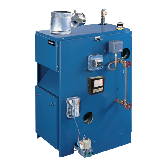
DIMENSIONS Figure 1 - Dimensions *Vent Damper Pressure ASME 26.50" Gauge Relief Pressure Valve Limit 4.75" Control Spill Switch Water Line Transformer 2.5 OD Glass Gauge Low Water 2.5 OD 36.375" Cutoff Probe Low Water Cutoff 29" 24.00" Rollout Switch 12.25"... -
Page 3: Ratings And Capacity
RATINGS AND CAPACITY Table 1 - Ratings and Capacities BOILER MODEL †Natural Gas NUMBER No. of Heating Sec. Intermittent Input Net AHRI Net AHRI Fuel Type Capacity AFUE(%) Ignition w/Vent Damper *MBTUH Rating *Mbh Rating Sq. Ft. *MBTUH Natural Gas 82.7 PSB-3D Propane... -
Page 4: Table Of Contents
TABLE OF CONTENTS Introduction Dimensions ..........2 Boiler is designed for use in closed heating systems where Ratings and Capacity ........3 all steam is returned as condensate and make-up water is Table of Contents ........4 minimal. Boiler is not designed for or intended for use in open systems using 100% make-up water. -
Page 5: Important Safety Information
IMPORTANT SAFETY INFORMATION Become familiar with symbols identifying potential Become familiar with symbols identifying potential WARNING hazards. hazards. Installing or venting a boiler or any other gas appliance with improper methods or materials could result in death or serious injury due to fire or to asphyxiation from poisonous gases such as carbon This is the safety alert symbol. - Page 6 IMPORTANT SAFETY INFORMATION FOR YOUR SAFETY READ BEFORE OPERATING Water 1st Degree Burn 2nd and 3rd Degree Burn Temperature Exposure Time For Exposure Time For An DANGER Setting An Adult Adult 120° F 1 minute 5 minutes 130° F 5 seconds 30 seconds 140°...
-
Page 7: Locating The Boiler
LOCATING THE BOILER Locating the Boiler Select level location as centralized with piping system, Table 2 - Minimum Clearance Dimensions and as near chimney as possible. 6" Place crated boiler at selected location. Remove all Rear 6" crate material. Please recycle responsibly. Control Side 7"... -
Page 8: System Piping
SYSTEM PIPING WARNING • Do not install shutoff valve between boiler and safety Burn and scald hazard. Safety relief valve could valve. discharge steam or hot water during operation. • Install union, if used, close to safety relief valve outlet. Install discharge piping per the following instructions. - Page 9 SYSTEM PIPING Consider near boiler piping as part of the boiler for proper For gravity return systems, the bottom of the lowest water level control and to produce dry steam. steam carrying pipe, be it a dry return, or the end of the steam main, must be at least 28”...
- Page 10 SYSTEM PIPING Figure 3 - Recommended Near Boiler Piping Using One Supply Tapping [3 & 4 Section Sizes] PN 14683003 Rev. O [10/01/2021]...
-
Page 11: Installation - System Piping
INSTALLATION - SYSTEM PIPING Figure 4 - Recommended Near Boiler Piping Using Two Supply Tappings [5 thru 9 Sections] Figure 5 - Chilled Water Piping VALVES A & B OPEN FOR HEATING; CLOSE FOR COOLING VALVES C & D CLOSE FOR HEATING; OPEN FOR COOLING PN 14683003 Rev. -
Page 12: Fresh Air For Combustion
FRESH AIR FOR COMBUSTION WARNING Room volume shall be greater than 21 cubic feet divided by ACH (air changes per hour) x Total Input Air openings to combustion area must not be [Mbh] obstructed. Follow instructions below, to maintain C. Refer to National Fuel Gas Code for opening adequate combustion air requirements between connected indoor spaces. -
Page 13: Chimney And Vent Pipe Connection
CHIMNEY AND VENT PIPE CONNECTION End of vent pipe must be flush with inside face of WARNING chimney flue. Use sealed-in thimble for chimney Installing or venting a boiler or any other gas connection. appliance with improper methods or materials could Horizontal run shall be as short as possible, however result in death or serious injury due to fire or to not longer than 3/4 the chimney height (HT) Figure 6,... - Page 14 CHIMNEY AND VENT PIPE CONNECTION Place in operation the appliance being inspected. Follow Figure 6 - Typical Masonry Chimney the lighting instructions. Adjust thermostat so appliance Requirements will operate continuously. Test for spillage at the draft hood relief opening after 5 minutes of main burner operation.
-
Page 15: Vent Damper Operation
VENT DAMPER OPERATION WARNING Figure 7 - Horizontal Installation Asphyxiation or burn hazard. Improper installation Horizontal Installation and operation of vent damper could result in serious Flow injury or death due to fire or to asphyxiation from poisonous gases such as carbon monoxide which is To Boiler Vent Damper odorless and invisible. -
Page 16: Gas Supply Piping
GAS SUPPLY PIPING CAUTION WARNING WHAT TO DO IF YOU SMELL GAS Fire, explosion, asphyxiation hazard. Verify boiler is equipped with propane gas orifices and gas valve • Do not try to light any appliance. is configured for propane. Failure to follow these •... -
Page 17: Electrical Wiring
ELECTRICAL WIRING Electronic Thermostats A. Some electronic thermostats may lose their WARNING memory or shut down. With probe type low water cutoff, this may occur each time low water cutoff Electrical shock hazard. Turn OFF electrical power detects low water condition. If this is the case, an supply at service panel before making electrical isolation relay is required for thermostat circuit. -
Page 18: Operating Instructions
OPERATING INSTRUCTIONS For Your Safety Read Before Operating STOP! Read the safety information on this page. WARNING Set the thermostat to lowest setting. If you do not follow these instructions Turn off all electric power to the appliance. exactly, a fire or explosion may result This appliance is equipped with an ignition device which causing property damage, personal injury automatically lights the pilot. -
Page 19: Operating Your Boiler
OPERATING YOUR BOILER Thermostat WARNING A. Set thermostat to desired room temperature. Burn Hazard. Never run water into a hot empty B. Set thermostat to lower setting if heat is not boiler. Failure to follow these instructions could required result in death or serious injury. C. -
Page 20: Checking And Adjusting
CHECKING AND ADJUSTING Adjust Pilot Burner Figure 14 - Igniter Pilot flame should surround 3/8” to 1/2” of pilot sensor. See Figure 14. To adjust Flame. Remove screw cover over pilot adjusting screw. See Figure 14. Insert small screwdriver and adjust flame as needed. Turn screw counterclockwise to increase flame, clock- wise to decrease. - Page 21 CHECKING AND ADJUSTING Adjust Steam Pressure Control Boiler Equipped With Optional WF-2U-24 Water Feeder • Steam pressure limit control (pressuretrol) shuts E. Continue thermostat call for heat after low water off gas to main burners when steam pressure in cut off recognizes low water condition. boiler reaches cut-off setpoint (i.e.
-
Page 22: Start-Up Cleaning
START-UP CLEANING Following final blow-down, allow boiler to cool. WARNING • Add fresh water slowly up to normal water line. Following service procedures must be performed • Start burners. by qualified service agent. Boiler owner shall not • Maintain at least 180°F for 15 minutes to remove attempt these steps. -
Page 23: General Maintenance
GENERAL MAINTENANCE Low Water Cut-Off Boiler Water Treatment Other Than Cleaners Low Water Cut-Off interrupts electrical current to burner In steam systems where system is tight, free from leaks, when water line in boiler drops to low level. and all steam is returned to boiler as condensate, amount of make up water is small. -
Page 24: Service Hints
SERVICE HINTS You may avoid inconvenience and service calls by checking these points before you call for service. CAUTION WHAT TO DO IF YOU SMELL GAS • Do not try to light any appliance. • Do not touch any electrical switch; do not use any phone in your building. -
Page 25: Wiring Diagrams
WIRING DIAGRAMS Figure 16 - Wiring Diagrams For Boilers With CG400 Probe Type Low Water Cut-Off Shown CG400 Terminals PSE802 To CG400 Cross Reference PSE802 CG400 If any of the original wire as supplied with this appliance must be replaced, it must be replaced with type 105°C Thermoplastic wire or its equivalent. - Page 26 WIRING DIAGRAMS Figure 17 - Wiring Diagrams For Boilers With 67D-1 Float Type Low Water Cut-Off If any of the original wire as supplied with this appliance must be replaced, it must be replaced with type 105°C Thermoplastic wire or its equivalent. PN 14683003 Rev.
-
Page 27: Controls And Accessories
CONTROLS AND ACCESSORIES SAFETY VALVE WATER FEEDER (Optional) Safety valve is designed to open automatically if boiler steam Model WF-2U-24 water feeder maybe used with either pressure exceeds pressure rating of valve (15 psig). Should of the low water cutoffs listed. Water feeder maintains it fail to open under this condition, shut down your boiler. -
Page 28: Appendix A - Vent Damper
APPENDIX A - VENT DAMPER A.1 Vent Damper Harness - Molex Plugs • If boiler ignites: Go to section B.2 "Vent Damper Troubleshooting Guide". • NOTE: Prior to replacing the damper, be sure the WARNING problem is not with wire connections between damper Do Not negate the action of any existing safety and wiring harness. -
Page 29: Appendix A - Vent Damper Troubleshooting
APPENDIX A - VENT DAMPER TROUBLESHOOTING A.2 Vent Damper Troubleshooting Guide WARNING Do Not negate the action of any existing safety orperational controls. Avoidance of these instructions could result in death or serious injury. When servicing controls, all wires must be Note labeled prior to disconnection. - Page 30 APPENDIX A - VENT DAMPER TROUBLESHOOTING For troubleshooting only. Verify damper is in Note open position. Use service switch to keep damper in open position. Place jumper between 2 & 3. If appliance fires, remove jumper and plug receptacle back into damper controller plug.
-
Page 31: Repair Parts
REPAIR PARTS JACKET - SECTION AND BASE PARTS THIS IS A REPAIR PARTS LIST - NOT A PACKAGING LIST 3 SECTION 4 SECTION 5 SECTION 6 SECTION 7 SECTION 8 SECTION 9 SECTION Description Part No. Part No. Part No. Part No. - Page 32 REPAIR PARTS NATURAL GAS BURNERS AND MANIFOLD PARTS LIST THIS IS A REPAIR PARTS LIST - NOT A PACKAGING LIST ELECTRONIC INTERMITTENT IGNITION (Shown) 3 SECTION 4 SECTION 5 SECTION 6 SECTION 7 SECTION 8 SECTION 9 SECTION DESCRIPTION PART NO. PART NO.
- Page 33 REPAIR PARTS *PROPANE GAS BURNERS AND MANIFOLD PARTS LIST THIS IS A REPAIR PARTS LIST - NOT A PACKAGING LIST *Use Conversion Kit - 550004168 550002740 ELECTRONIC INTERMITTENT IGNITION (Shown) 550002740 550002740 550002740 550002740 550002740 550002740 550002740 3 SECTION 4 SECTION 5 SECTION 6 SECTION 7 SECTION...
- Page 34 REPAIR PARTS BOILER CONTROLS AND PIPING Part Description ¾" Safety Relief Valve 1570001 ¾" Coupling 1150001 ¾" x 6-½" Nipple 14607002 Steam Pressure Gauge Kit 550003355 AT-140D Transformer, 24 Volt 14662305 PA-404A Pressuretrol 14662015 Glass Water Gauge Set (used with PS-802 LWCO) 14622005 Glass Water Gauge Set (used with 67D-1 LWCO) 14622010...
-
Page 35: Check Out Certificate
INSTALLATION AND CHECK-OUT CERTIFICATE Boiler Model Serial # Date Installed___________ Measured BTU/HR input____________ Installation instructions have been followed Checkout procedure and adjustments performed Maintenance and Service issues reviewed with owner/ maintenance person Installation booklet affixed on or adjacent to boiler Installer (Company) Address Phone... - Page 36 2201 Dwyer Avenue, Utica, NY 13501 All specifications subject to change without notice. Tel. 800 325 5479 ©2021 ECR International, Inc. www.ecrinternational.com...
Need help?
Do you have a question about the Dunkirk PLYMOUTH STEAM 2 Series and is the answer not in the manual?
Questions and answers