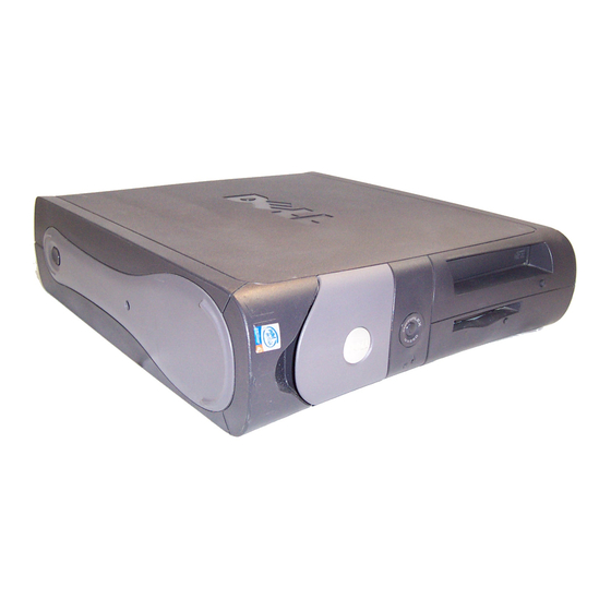
Dell OptiPlex GX260 Disassembly
Hide thumbs
Also See for OptiPlex GX260:
- System user's manual (236 pages) ,
- Service manual (100 pages) ,
- User manual (31 pages)
Table of Contents
Advertisement
Quick Links
Advertisement
Table of Contents

Related Manuals for Dell OptiPlex GX260


Summary of Contents for Dell OptiPlex GX260
- Page 1 Computer disassembly Dell OptiPlex GX260...
- Page 2 Overview Working with the Dell OptiPlex GX260 • Disassemble • Identify the parts • Reassemble...
-
Page 3: Precautionary Measures
Precautionary measures NOTICE: To help avoid possible damage to the system board, wait 5 seconds (or wait until the standby light is extinguished) after turning off the computer and unplugging the power cord before removing a component from the system board or disconnecting a device from the computer. -
Page 4: Back Panel
Back panel Input/Output (I/O) ports Parallel port Serial port External Video Graphics Array (VGA) port PS/2 keyboard PS/2 mouse RJ-45 (Ethernet socket) Universal Serial Bus (USB) 2.0 (4 separate ports) Stereo line-in (mini-jack) Microphone-in (mini-jack) Speakers/line-out (mini-jack) External VGA (Graphics card) S-Video out (Graphics card) AC-Power... -
Page 5: Opening The Cover
Opening the cover 1. Security cable slot 2. Pad lock ring 3. Button... -
Page 6: Inside The Computer
Inside the computer 1. Hard drive 2. Chassis intrusion switch 3. Card cage 4. Power supply 5. Heat sink and blower assembly 6. System board 7. Floppy drive 8. Compact Disc (CD)/ Digital Versatile Disc (DVD) drive... - Page 7 Humor? There are 10 kinds of people: Those who can read binary and those who cannot (10 in binary base is 2 in decimal base)
- Page 8 Representing and storing data Binary digit • Binary digit (bit) Status – Has 2 possible states – How many different combinations can you have with your representation? • Byte (8 bits, 2^7=256 combinations) – Used to represent characters – A typical college essay has 250 words per page, a word has on average 5.5 characters.
- Page 9 Binary numbers – base 2 Binary: 1010=1000+0000+0010+0000 Decimal: 10= 1*8+ 0*4+ 1*2+ 0*1 General: a +...+a Binary value 1000 0100 0010 0001 Position Weight (base^position) Decimal value Binary (Base 2) 0000 0001 0010 0011 0100 0101 0110 0111 1000 1001 1010 1011 1100...
-
Page 10: Computer Cables
Computer cables 1. CD/DVD drive audio cable 2. CD/DVD drive data cable 3. Floppy-drive data cable 4. Control-panel cable 5. Integrated Drive Electronics (IDE) data cable (hard drive) - Page 11 Buses • Transfer data from the I/O devices to the Central Processing Unit (CPU) • Different buses have different specifications e.g – Width, number of bits in one unit, – Speed, cycles per second.
- Page 12 PCI Card Cage • Peripheral Component Interconnect (PCI card) • Standards for the connector and motherboard slot...
- Page 13 Removing AGP or DVI card • Accelerated Graphics Port (AGP) Graphics card...
-
Page 14: Removing Hard Drive
Removing Hard drive 1. Hard-drive cable 2. Power cable Hard Drive (HDD) 20 – 80GB for the OptiPlex GX260 models... - Page 15 Removing Floppy Drive 1. Power cable 2. Floppy-drive cable Floppy Disk Drive (FDD) 1.44MB...
- Page 16 Removing a DVD 1. Audio cable 2. CD/DVD drive cable 3. Power cable CD typically 700MB 4.7GB (Single layer) 8.5GB (Double layer)
- Page 17 Removing front I/O 1. I/O cable 2. Control-panel cable 3. Front audio cable 4. Internal speaker cable...
- Page 18 Memory • Each byte in the memory has an address. Data is stored and retrieved by going to the address in the memory • Types of Memory – Random Access Memory (RAM) • Is reset when power is turned off –...
- Page 19 RAM Memory chip 128 MB double data rate synchronous dynamic random access memory (DDR SDRam) 2 dual in-line memory module (DIMM) slots Max RAM memory capacity 1GB...
- Page 20 Processing • Each processor has an instruction set – Different processors have different instruction sets • During a machine cycle (Clock cycle) the Control unit and Arithmetic-Logic Unit (ALU) Fetch instructions from memory and load to instruction register Control unit decodes the instructions in the register ALU executes the instructions Store the result in a register or memory –...
- Page 21 Heat sink/Microprocessor Intel Pentium 4 2.53GHz, L2 cache 512k...
-
Page 22: Replacing The Battery
Replacing the battery 1. Battery... -
Page 23: Power Supply
Power supply • 180 Watts power supply... -
Page 24: System Board
System board Floppy drive connector (DSKT) Internal speaker (SPEAKER) CD/DVD drive connector (IDE2) Hard drive connector (IDE1) Front-panel connector (FRONTPANEL) Standby power light (AUX_PWR) AGP card connector (AGP) PCI card connectors (PCI1, PCI2) Front-panel audio cable connector (FRONTAUDIO) CD drive audio cable connector (CD_IN) Telephony connector (MODEM) Power connector (12VPOWER) Second serial connector (SER2) - Page 25 All parts 1. System board 2. Heat sink 3. Microprocessor 4. AGP Graphics card 5. Memory 6. Floppy drive 7. CD/DVD drive 8. PCI card cage 9. Hard drive 10. Power supply...
-
Page 26: Putting It All Together
Putting it all together • Input data • Process data • Store data • Output data...
Need help?
Do you have a question about the OptiPlex GX260 and is the answer not in the manual?
Questions and answers