Advertisement
SIDE A - 10/01/03
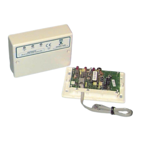
CCT864 SYSTEM Q INTELLEGENT TIME & DATE GENERATOR INSTRUCTIONS
Features
• GMT time stamp saves UK time adjustment for
Summer/Winter.
• Day & Date Stamp.
• Indicates Camera Number currently displayed for area
identification.
• Displays system mode i.e. auto, manual or alarm.
• Battery back-up in the event of a mains failure.
• Quick and easy installation via a plug-in cable supplied.
Fitting
Remove the two securing screws from the cover and remove the cover. Find a flat dry location close to the
control unit ensuring that the supplied Grey cable is long enough to reach between the time and date generator
and the control unit. The unit can be fitted to the wall using the pre-drilled holes with two screws in opposite
corners or four screws using all holes. Position the unit so that the LED's are at the top and secure firmly to the
wall.
Wiring
To 4 camera systems
Remove the cover from the control unit and loosen the clamping bar on both the control unit and the time and
date generator. Carefully plug one end of the supplied grey lead into the socket on the Time & Date unit
marked 'To control or expander'. The spring clip should be uppermost as the plug is inserted. When fully
home, a positive click will be heard. Plug the other end of this lead into the grey socket on the control unit
between camera port-4 and the intelligent remote terminals. With the lead in place, replace and tighten the
clamping bars so that the cables cannot be pulled out. With the grey lead in place, the jumper above the socket
must be removed. This is marked on the control unit board as "Remove when plug fitted". The cover can be
replaced after wiring.
To 8 camera systems
Remove the cover from the expander unit (CCT861) and loosen the clamping bar on both the expander unit and
the time and date generator. Carefully plug one end of the supplied grey lead into the socket on the Time &
Date unit marked 'To control or expander'. As this is inserted the spring clip should be uppermost, once home a
positive click will be heard. Plug the other end of this cable into the socket of the expander unit marked 'to on
screen display' which is found next to the socket to the master controller. Once the lead is in place, replace and
tighten the clamping bar so as to prevent the plugs from being pulled out. With the lead in place, the jumper to
the right of the socket marked 'Remove if OSD fitted,' must be removed.
Setting
The unit is setup using two buttons in the centre of the board, marked SEL and ADJ. All adjustments are made
through an on-screen menu system accessed though these buttons.
✽ System Q Ltd ✽ Q House ✽ The Green ✽ Hasland ✽ Chesterfield ✽ S41 0LJ ✽
SEL
-
Is an abbreviation for - Select
ADJ
-
Is an abbreviation for - Adjust
✽ Sales 01246 200 000 ✽ Fax 01246 222 888 ✽
Document No: XXXCCT864/1
Advertisement
Table of Contents

Subscribe to Our Youtube Channel
Related Manuals for System Q CCT864

Summary of Contents for System Q CCT864
- Page 1 Is an abbreviation for - Select Is an abbreviation for - Adjust ✽ System Q Ltd ✽ Q House ✽ The Green ✽ Hasland ✽ Chesterfield ✽ S41 0LJ ✽ ✽ Sales 01246 200 000 ✽ Fax 01246 222 888 ✽...
- Page 2 All specifications are approximate. System Q Ltd reserves the right to change any product specification or features without notice. Whilst every effort is made to ensure that these instructions are complete and accurate, System Q Ltd. cannot be held responsible in any way for any losses no matter how they arise from errors or omissions in these instructions.
Need help?
Do you have a question about the CCT864 and is the answer not in the manual?
Questions and answers