Advertisement
Quick Links
FX-NAC Analog NAC Module
Installation Sheet
Operation
The module is an analog addressable device used to connect a
supervised output circuit to a signal riser. The output wiring is
monitored for open and short circuits. A short circuit causes the
module to inhibit the activation of the audible/visual signal circuit so the
riser is not connected to the wiring fault. Upon command from the
control panel, the module connects the output circuit to the riser input.
The output circuit energizes a riser to operate polarized audible and
visual signals. The module can be used for connection of a Class A or
Class B (with EOL) output notification appliance circuit (NAC).
The device address is set using the two rotary switches located on the
front of the module. One device address is required.
The module is configured to operate as a Genesis
Audible/Visual/Silence device type from the factory. The module can
also be configured for other device types through front panel
programming or the configuration utility. Refer to the applicable control
panel technical reference manual for a list of available device types.
Genesis Audible/Visual/Silence: Used with Genesis and Enhanced
Integrity horns and strobes. Genesis and Enhanced Integrity
appliances maintain synchronization per UL 1971. For Genesis
devices, this configuration allows connected horns to be silenced while
strobes on the same two-wire circuit continue to flash until the panel is
reset.
LED operation
The module provides a bicolor LED that shows its status.
Normal: Green LED flashes
Active: Red LED flashes
Installation
Install and wire this device in accordance with applicable national and
local codes, ordinances, and regulations.
WARNINGS
•
This module will not operate without electrical power. As fires
frequently cause power interruption, you should discuss further
safeguards with your local fire protection specialist.
Note:
The module is shipped from the factory as an assembled unit; it
contains no user-serviceable parts and should not be disassembled.
P/N 3101085-EN • REV 006 • ISS 03JUL18
To install the module:
1. Verify that all field wiring is free of opens, shorts, and ground
faults.
2. Make all wiring connections as shown in "Wiring" and Figure 3.
3. Set the module address. Refer to the panel technical reference
manual for a list of valid addresses.
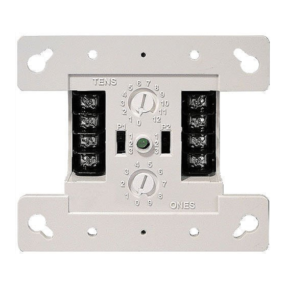
Use a screwdriver to adjust the two rotary switches on the front of
the module. Set the TENS rotary switch (0 through 12) for the 10s
and 100s digit and the ONES rotary switch for the 0 through 9
digit. For example: device address 21, set TENS rotary switch to 2
and set the ONES rotary switch to 1 (see Figure 1).
4. Mount the module on the electrical box using screws provided with
the electrical box.
5. Mount the wall plate on the module using #4-24 × 1/2 in. (13 mm)
self-tapping screws.
Figure 1: Module address
Figure 2: Module installation
4-24
screws
Wall plate
Wiring
Wire the device as shown in Figure 3. Be sure to observe the polarity
of the wires.
Insert
screwdriver
here
Compatible
electrical box
Module
Screw
1 / 2
Advertisement

Related Manuals for United Technologies Kidde FX-NAC


Summary of Contents for United Technologies Kidde FX-NAC
- Page 1 To install the module: 1. Verify that all field wiring is free of opens, shorts, and ground faults. 2. Make all wiring connections as shown in “Wiring” and Figure 3. 3. Set the module address. Refer to the panel technical reference FX-NAC Analog NAC Module manual for a list of valid addresses.
- Page 2 (Sizes 16 and 18 AWG are preferred) Specifications Contact information Communication line Maximum 20.6 V peak-to-peak voltage For contact information, see www.kiddelifesafety.com Current © 2018 United Technologies Corporation Standby 280 µA All rights reserved. Activated 100 µA Ground fault impedance 10 kΩ Operating environment Temperature 32 to 120°F (0 to 49°C)
Need help?
Do you have a question about the Kidde FX-NAC and is the answer not in the manual?
Questions and answers