Table of Contents
Advertisement
Quick Links
Advertisement
Table of Contents

Subscribe to Our Youtube Channel
Related Manuals for Arcteq AQ-E215

Summary of Contents for Arcteq AQ-E215
- Page 1 AQ-E215 Energy management IED Instruction manual...
-
Page 2: Table Of Contents
5.1. Functions included in AQ-E215 ........ - Page 3 7.1. Connections of AQ-E215 ........
- Page 4 11. Contact and reference information ..........© Arcteq Relays Ltd...
- Page 5 Nothing contained in this document shall increase the liability or extend the warranty obligations of the manufacturer Arcteq Relays Ltd. The manufacturer expressly disclaims any and all liability for any damages and/or losses caused due to a failure to comply with the instructions contained herein or caused by persons who do not ful l the aforementioned requirements.
- Page 6 AQ-E215 Instruction manual Version: 2.01 Copyright Copyright © Arcteq Relays Ltd. 2018. All rights reserved. © Arcteq Relays Ltd...
-
Page 7: Manual Revision Notes
- Added double ST 100 Mbps Ethernet communication module and Double RJ45 10/100 Mbps Ethernet communication module descriptions 1.2. Version 1 revision notes Revision 1.00 Date 19.1.2015 Changes - The rst revision for AQ-E215 IED. Revision 1.01 Date 12.1.2016 Changes - Added digital input operation description. Revision 1.02... - Page 8 - Ring-lug CT card option description added - Order code revised Revision 1.06 Date 14.8.2018 Changes - Added mA output option card description and ordercode Revision 1.07 Date 18.1.2019 Changes - HMI display technical data added © Arcteq Relays Ltd...
-
Page 9: Abbreviations
RMS – Root mean square SF – System failure TMS – Time multiplier setting TRMS – True root mean square VAC – Voltage alternating current VDC – Voltage direct current SW – Software uP - Microprocessor © Arcteq Relays Ltd... -
Page 10: General
Version: 2.01 3. General The AQ-E215 energy management IED is a member of the AQ-200 product line. The hardware and software are modular: the hardware modules are assembled and con gured according to the application's I/O requirements and the software determines the available functions. This manual describes the speci c application of the AQ-E215 energy management IED. -
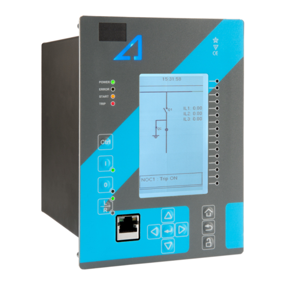
Page 11: Ied User Interface
The sixteen freely con gurable LEDs are located on the right side of the display. Their activation and color (green or yellow) are based on the settings the user has put in place in the software. © Arcteq Relays Ltd... -
Page 12: Mimic And Main Menu
) takes you to the password menu where you can enter the passwords for the various user levels (User, Operator, Con gurator, and Super-user). 4.2.2. Navigation in the main con guration menus All the settings in this device have been divided into the following six (6) main con guration menus: General Protection Control © Arcteq Relays Ltd... -
Page 13: General Menu
Figure. 4.3. - 4. Device info. The Device info tab in the General menu displays the following information: The set name and location of the device. The device's serial number and software version. The hardware con guration (i.e. the order code). © Arcteq Relays Ltd... -
Page 14: Control Menu
In this submenu you can also activate and disable the controlled objects. As with control functions, all objects are disabled by default. All activated objects can be viewed in the Objects submenu (see the section "Objects" below for more information). © Arcteq Relays Ltd... - Page 15 Setting group 1 (SG1) has the highest priority, while Setting group 8 (SG8) has the lowest priority. Setting groups can be controlled with pulses or with both pulses and static signals (see the image below). Figure. 4.4. - 8. Example of group changing. © Arcteq Relays Ltd...
- Page 16 Each activated object is visible in the Objects submenu. By default all objects are disabled unless speci cally activated in the Controls enabled submenu. Each active object has four sections in their submenus: "Settings", "Application control" ("App contr"), "Registers" and "Events". SETTINGS Figure. 4.4. - 10. Settings section. © Arcteq Relays Ltd...
- Page 17 REGISTERS AND EVENTS You can view the last twelve (12) registers of the control functions and objects through the "Registers"subsection. You can view the events speci c to each control function and controlled object through the "Events" subsection. © Arcteq Relays Ltd...
- Page 18 "Device I/O matrix", "Programmable control switch" and "Logic signals". Please note that digital inputs, logic outputs, protection stage status signals (START, TRIP, BLOCKED, etc.) as well as object status signals can be connected to an output relay or to LEDs in the Device I/O matrix © Arcteq Relays Ltd...
- Page 19 "Event masks" subsection you can determine which events are masked –and therefore visible in the event list– and which are not. Figure. 4.4. - 14. Digital outputs subsection. All settings related to digital outputs can be found in the "Digital outputs" section. © Arcteq Relays Ltd...
- Page 20 The "LED settings" subsection allows you to modify the individual label text attached to an LED ("LED description settings"); that label is visible in the LED quick displays and the matrices. You can also modify the color of the LED ("LED color settings") between green and yellow; by default all LEDs are green. © Arcteq Relays Ltd...
- Page 21 These signals can be used in a variety of situations, such as for controlling the logic program, for function blocking, etc. You can name each switch and set the access level to determine who can control the switch. © Arcteq Relays Ltd...
-
Page 22: Communication Menu
(can be found in the Connections submenu). As a standard, the devices support the following communication protocols: NTP, IEC 61850, Modbus/TCP, Modbus/RTU, IEC 103, IEC 101/104, SPA and Modbus/IO. You can also have other protocols with additional, speacialized communication interface modules. © Arcteq Relays Ltd... - Page 23 NOTE! When communicating with a device through a front Ethernet port connection, the IP address is always 192.168.66.9. Protocols Figure. 4.5. - 20. View of the Protocols submenu. The Protocols submenu offers access to the various communication protocol con guration menus: © Arcteq Relays Ltd...
-
Page 24: Measurement Menu
Transformers submenu, while the system nominal frequency is speci ed in the Frequency submenu. Other submenus are mainly for monitoring purposes. Transformers Figure. 4.6. - 21. Transformers submenu. © Arcteq Relays Ltd... - Page 25 When "Sampling mode" is set to "Tracking", the device uses the measured frequency value as the system nominal frequency. There are three reference measuring points; the order of the reference points can be changed. © Arcteq Relays Ltd...
- Page 26 (and then set the parameters) for the Energy dose counter mode. "Power measurements" displays all three-phase powers as well as the powers of individual phases. "Energy measurements" displays the three-phase energy as well as the energies of the individual phases. © Arcteq Relays Ltd...
-
Page 27: Monitoring Menu
( Disturbance REC ) and accessing the device diagnostics ( Device diagnostics ). The available monitoring functions depend on the type of the device in use. Figure. 4.7. - 25. Monitoring menu view. © Arcteq Relays Ltd... - Page 28 Con guring monitor functions is very similar to con guring protection stages. They, too, have the ve sections that display information ("Info"), set the parameters ("Settings"), show the inputs and outputs ("I/O") and present the events and registers ("Events" and "Registers"). © Arcteq Relays Ltd...
- Page 29 "Recording mode" can be selected to replace the oldest recording ("FIFO") or to keep the old recordings ("FILO"). "Analog channel samples" determines the sample rate of analog channels, and it can be selected to be 8/16/32/62 samples per cycle. © Arcteq Relays Ltd...
- Page 30 If you see something out of the ordinary in the Device diagnostics submenu and cannot reset it, please contact the closest representative of the manufacturer or the manufacturer of the device itself © Arcteq Relays Ltd...
-
Page 31: Con Guring User Levels And Their Passwords
Operator: Can view any menus and settings but cannot change any settings BUT can operate breakers and other equipment. Con gurator: Can change most settings such as basic protection pick-up levels or time delays, breaker control functions, signal descriptions etc. and can operate breakers and other equipment. © Arcteq Relays Ltd... - Page 32 AQ-E215 Instruction manual Version: 2.01 Super user: Can change any setting and can operate breakers and other equipment. NOTE! Any user level with a password automatically locks itself after half an hour (30 minutes) of inactivity. © Arcteq Relays Ltd...
-
Page 33: Functions
Version: 2.01 5. Functions 5.1. Functions included in AQ-E215 The AQ-E215 energy management protection IED includes the following functions as well as the number of stages for those functions. The mentioned fault indicating functions are accessible through the Fault monitor tab in the Monitoring menu. Table. 5.1. - 1. Fault indicating functions of AQ-E215. - Page 34 In modern protection devices this scaling calculation is done internally after the current transformer's primary current, secondary current and motor nominal current are set. © Arcteq Relays Ltd...
- Page 35 - CT secondary: 5 A - I0CT secondary: 1 A - the phase currents are connected to the I01 residual via a Holmgren connection - the starpoint of the phase current CT's secondary current is towards the line © Arcteq Relays Ltd...
- Page 36 If the protected object's nominal current is chosen to be the basis for the per-unit scaling, the option "Object in p.u." is selected for the "Scale meas to In" setting (see the image below). Figure. 5.2.1. - 33. Setting the phase current transformer scalings to the protected object's nominal current. © Arcteq Relays Ltd...
- Page 37 The rst of the two images shows how the measurements are displayed when the CT primary values are the basis for the scaling; the second shows them when the protected object's nominal current is the basis for the scaling. © Arcteq Relays Ltd...
- Page 38 Zero sequence CT scaling (ZCT scaling) is done when a zero sequence CT instead of a ring core CT is part of the measurement connection. In such a case the zero sequence CT should be connected to the I02 channel which has lower CT scaling ranges (see the image below). © Arcteq Relays Ltd...
- Page 39 The residual I0CT scaling is set according to the zero sequence CT's ratings, in this case 200/1.5 mA (see the image below). Based on these values, the earth fault protection setting (1 × I0n) makes the function pick-up when the primary current is at 200 mA (see the image below). © Arcteq Relays Ltd...
- Page 40 The measured current amplitude does not match one of the measured phases./ Check the wiring connections between the injection device or the CTs and the relay. The calculated I0 is measured even though it should not. © Arcteq Relays Ltd...
- Page 41 I2: 0.67 × In / -60.00 deg I0Calc: 0.67 × In / 60.00 deg Solution options: - switch the wires between the connectors 3 and 4 in the CT module - invert the polarity of IL2 ( Measurement → Transformers → Phase CT scaling ) © Arcteq Relays Ltd...
- Page 42 IL3: 1.00 × In / 240.00 deg Sequence currents: I1: 0.00 × In / 0.00 deg I2: 1.00 × In / 0.00 deg I0Calc: 0.00 × In / 0.00 deg Solution: - switch the wires between the connectors 1 and 3 in the CT module © Arcteq Relays Ltd...
- Page 43 1…25 Nominal 0.001 100.000 The nominal current of the protected object. This setting is only visible if the option 000.000 current In "Object In p.u." has been selected in the "Scale meas. to In" setting. © Arcteq Relays Ltd...
- Page 44 A relay feedback value; the calculated scaling factor that is the ratio between the scaling primary current and the secondary current. factor P/S Measurements The following measurements are available in the measured current channels. Table. 5.2.1. - 10. Per-unit phase current measurements. Name Range Step Description © Arcteq Relays Ltd...
- Page 45 Table. 5.2.1. - 15. Primary residual current measurements. Name Range Step Description Primary residual 0.00…1 000 0.01 The primary fundamental frequency RMS current measurement from the current I0x 000.0 A residual current channel I01 or I02. ("Pri.Res.curr.I0x") © Arcteq Relays Ltd...
- Page 46 000.0 A sequence current. ("Pri.Neg.seq.curr.") Primary zero sequence 0.00…1 000 0.01 The primary measurement from the calculated zero sequence current 000.0 A current. ("Pri.Zero seq.curr.") Table. 5.2.1. - 20. Secondary sequence current measurements. Name Range Step Description © Arcteq Relays Ltd...
-
Page 47: Voltage Measurement And Scaling
The measured values are processed into the measurement database and they are used by measurement and protection functions (the protection function availability depends of the relay type). It is essential to understand the concept of voltage measurements to be able to get correct measurements. © Arcteq Relays Ltd... - Page 48 VT ratings. In the gure below, three line-to-neutral voltages are connected along with the zero sequence voltage; therefore, the 3LN+U4 mode must be selected and the U4 channel must be set as U0. Other possible connections are presented later in this chapter. © Arcteq Relays Ltd...
- Page 49 This selection is de ned in the "Measured magnitude" of each protection stage menu separately ( Protection → Voltage → [protection stage menu] → INFO ; see the image below). The number of available protection functions depends on the relay type. © Arcteq Relays Ltd...
- Page 50 Protection → Voltage → [protection stage menu] → Settings ). Fault loops are either line-to-line or line-to-neutral according to the "Measured magnitude" setting. As a default, the activation of any one voltage trips the voltage protection stage. Figure. 5.2.2. - 42. Selecting the operating mode. © Arcteq Relays Ltd...
- Page 51 Please note that U0 can only be measured by using a single channel. In the image below is an example of 2LL+U0+SS, that is, two line-to-line measurements with the zero sequence voltage and voltage from side 2 for Synchrocheck. Since U0 is available, line-to-neutral voltages can be calculated. © Arcteq Relays Ltd...
- Page 52 The VT scaling has been set to 20 000 : 100 V. The U4 channel measures the zero sequence voltage which has the same ratio (20 000 : 100 V). © Arcteq Relays Ltd...
- Page 53 Table. 5.2.2. - 24. Settings of the VT scaling. Name Range Step Default Description Voltage 0: 3LN+U4 measurement 1: 3LL+U4 The relay's voltage wiring method. The voltages are scaled according the mode 3LN+U4 set voltage measurement mode. ("Voltage 2LL+U3+U4 meas mode") © Arcteq Relays Ltd...
- Page 54 A relay feedback value; the calculated scaling factor that is the ratio factor P/S between the primary voltage and the secondary voltage. VT scaling A relay feedback value; the scaling factor for the primary voltage's per- factor p.u. Pri unit value. © Arcteq Relays Ltd...
- Page 55 The phase angle measurement from each of the four voltage inputs. Table. 5.2.2. - 28. Per-unit sequence voltage measurements. Name Range Step Description Positive sequence 0.00…500.0 × 0.01 × The measurement (in p.u.) from the calculated positive sequence voltage voltage. ("Pos.seq.Volt.p.u.") © Arcteq Relays Ltd...
- Page 56 System voltage 0.00… magnitude 1 000 0.01 The primary fundamental frequency RMS line-to-line UL23 voltage (measured or UL23 000.00 calculated). You can also select the row where the unit for this is kV. ("System volt UL23 mag") © Arcteq Relays Ltd...
- Page 57 System voltage angle 0.00… 0.01 UL23 360.0 The primary line-to-line angle UL23 (measured or calculated). ("System volt UL23 ang") System voltage angle 0.00… 0.01 UL31 360.0 The primary line-to-line angle UL23 (measured or calculated). ("System volt UL31 ang") © Arcteq Relays Ltd...
-
Page 58: Power And Energy Calculation
Energy measurement calculates magnitudes for active and reactive energy. Energy can flow to the forward direction (exported) or to the reverse direction (imported). If a unit has more than one CT measurement module, the user can choose which module's current measurement is used by the power calculation. © Arcteq Relays Ltd... - Page 59 Figure. 5.2.3. - 49. Three-phase reactive power (Q) calculation. Active power can be to the forward or the reverse direction. The direction of active power can be indicated with the power factor (Cos (φ), or Cosine phi), which is calculated according the following formula: © Arcteq Relays Ltd...
- Page 60 Most power and energy measurement problems are usually related to the same issues (i.e. wiring errors, wrong measurement modes, faulty frequency settings, etc.). Settings Table. 5.2.3. - 35. Power and energy measurement settings Name Range Step Default Description © Arcteq Relays Ltd...
- Page 61 Table. 5.2.3. - 36. Energy Dose Counter 1 settings Name Range Step Default Description Energy dose 0: Disabled 0: Disabled Enables/disables energy dose counters generally. counter 1: Activated mode DC 1…4 0: Disabled Enables/disables the energy dose counter 1…4 0: Disabled enable 1: Enabled individually. © Arcteq Relays Ltd...
- Page 62 The following energy calculations are available when the voltage and the current cards are available. Please note that the unit pre x is determined by the user's selection between 'kilo' and 'mega' in "Three- phase energy pre x ("E 3ph M or k")" under the general "Power and energy measurement settings". © Arcteq Relays Ltd...
- Page 63 Here is an example of power calculation. Both wiring methods (line-to-line and line-to-neutral) are checked with the same signal injection. The voltage scaling is set to 20 000 : 100 V and the current scaling is set to 1000 : 5 A. © Arcteq Relays Ltd...
- Page 64 L2 Cos 0.77 L3 Cos 0.99 3PH Cos 0.87 Voltages (line-to-line): Currents: = 100.00 V, 30.00° = 2.5 A, 0.00° L12 L1 = 100.00 V, -90.00° = 2.5 A, -120.00° L23 L2 = 2.5 A, 120.00° © Arcteq Relays Ltd...
-
Page 65: Frequency Tracking And Scaling
5 %.The gures also show that when the frequency is tracked and the sampling is adjusted according to the detected system frequency, the measurement accuracy has an approximate error of -0.1...- 0.2 % in the whole frequency range. © Arcteq Relays Ltd... - Page 66 This has been achieved by adjusting the sample rate of the measurement channels according to the measured system frequency; this way the FFT calculation always has a whole power cycle in the buffer. The measurement accuracy is further improved by Arcteq's patented calibration algorithms that calibrate the analog channels against eight (8) system frequency points for both magnitude and angle.
-
Page 67: Fault Indicating Functions
The non-directional overcurrent function uses a total of eight (8) separate setting groups which can be selected from one common source. The operational logic consists of the following: © Arcteq Relays Ltd... - Page 68 0.10…40.00 × I 0.01 × I 1.20 × I Pick-up setting The pick-up activation of the function is not directly equal to the START signal generation of the function. The START signal is allowed if the blocking condition is not active. © Arcteq Relays Ltd...
-
Page 69: Non-Directional Earth Fault (I0>; 50N)
The operational logic consists of the following: input magnitude selection input magnitude processing saturation check threshold comparator output processing. The inputs for the function are the following: operating mode selections setting parameters digital inputs and logic signals measured and pre-processed current magnitudes. © Arcteq Relays Ltd... - Page 70 Description 8642 EMON1 I0> (50N) Detect ON 8643 EMON1 I0> (50N) Detect OFF The function registers its operation into the last twelve (12) time-stamped registers. The table below presents the structure of the I0> function's register content. © Arcteq Relays Ltd...
-
Page 71: Directional Overcurrent (Idir>; 67)
Table. 5.3.3. - 52. Measurement inputs of the Idir> function. Signal Description Time base IL1RMS Fundamental RMS measurement of phase L1 (A) current 5 ms IL2RMS Fundamental RMS measurement of phase L2 (B) current 5 ms © Arcteq Relays Ltd... - Page 72 0.01 × I 1.20 × I The pick-up setting. The pick-up activation of the function is not directly equal to the START signal generation of the function. The START signal is allowed if the blocking condition is not active. © Arcteq Relays Ltd...
- Page 73 Table. 5.3.3. - 55. Register content. Event Fault Operating Max I Date and time Used SG code type angle Setting dd.mm.yyyy 8644-8645 L1-G… The ratio between the highest phase current 0...250° group 1...8 hh:mm:ss.mss Descr. L1-L2-L3 and the pick-up value. active. © Arcteq Relays Ltd...
-
Page 74: Directional Earth Fault (I0Dir>; 67N)
Fundamental RMS value of the calculated residual current from the three phase currents 5 ms U0RMS Fundamental RMS measurement of zero sequence voltage measurement input U0 5 ms U0Calc Fundamental RMS value of the calculated zero sequence voltage from the three phase voltages 5 ms © Arcteq Relays Ltd... - Page 75 The I0 angle blinder. This setting is only visible when "Earthed" or "I0 & I0 broad range I0 angle blinder -90.0…0.0 deg 0.1 deg -90 deg Cos mode" is the selected earthing type. © Arcteq Relays Ltd...
- Page 76 There are many bene ts to a Petersen coil earthed network. The amount of automatic reclosing is highly decreased and the maintenance of the breakers is therefore diminished. Arc faults die on their own, and cables and equipment suffer less damage. In emergency situations a line-to-earth fault can be used for a speci c time. © Arcteq Relays Ltd...
- Page 77 Directly earthed or small impedance network Figure. 5.3.4. - 53. Angle tracking of I0dir> function (directly earthed or small impedance network). © Arcteq Relays Ltd...
- Page 78 Finally, in a compensated network protection the relay with traditional algorithms may sporadically detect an earth fault in a long healthy feeder due to CT errors. For all these reasons, Arcteq has developed an improved alternative to these traditional directional earth fault protections.
- Page 79 No extra parameterization is required compared to the traditional method. The multi-criteria algorithm can be tested with COMTRADE les supplied by Arcteq. The function requires a connection of three-phase currents, residual current and residual voltage to operate correctly.
-
Page 80: Intermittent Earth Fault (I0Int>; 67Nt)
Handling these unique characteristics requires a completely different set of tools than what traditional directional earth fault protection can offer. The following gures present three intermittent earth fault situations experienced by relays in a substation. © Arcteq Relays Ltd... - Page 81 AQ-E215 Instruction manual Version: 2.01 Figure. 5.3.5. - 56. An intermittent earth fault in a medium size network tuned close to resonance, as seen by a faulty feeder relay. © Arcteq Relays Ltd...
- Page 82 AQ-E215 Instruction manual Version: 2.01 Figure. 5.3.5. - 57. An intermittent earth fault in a network tuned close to resonance, as seen by a healthy feeder relay. © Arcteq Relays Ltd...
- Page 83 When analyzing the situation from the point of view of normal directional earth fault protection, the result may be an expected trip in a faulty feeder, a false trip in a healthy feeder, or no trip whatsoever, all equally probable. © Arcteq Relays Ltd...
- Page 84 (if start events are considered disturbing), or if directional non-intermittent earth fault protection is set to a faster operating time than intermittent earth fault protection. © Arcteq Relays Ltd...
- Page 85 The START signal is allowed if the blocking condition is not active and if the threshold of the admittance delta calculated by the input signal exceeds these settings: I0 Detect spike > = set admittance delta threshold U0 Detect spike > = set admittance delta threshold. © Arcteq Relays Ltd...
- Page 86 8651 of forward of reverse cumulative forward group 1...8 hh:mm:ss.mss forward Descr. start in this start in this spikes. If 0, there are active. operating (faulty feeder) fault. fault. enough spikes to trip. time. spikes. © Arcteq Relays Ltd...
-
Page 87: Undervoltage (U<; 27)
Table. 5.3.6. - 65. Analog magnitudes used by the U< function. Signal Description Time base Fundamental RMS measurement of voltage U 5 ms Fundamental RMS measurement of voltage U 5 ms Fundamental RMS measurement of voltage U 5 ms © Arcteq Relays Ltd... - Page 88 (12) recorded events for all provided instances separately. Table. 5.3.6. - 68. Register content. Event Fault Date and time Used SG meas code type dd.mm.yyyy 8652-8655 A…A- The ratio between the measured voltage and the Setting group 1...8 hh:mm:ss.mss Descr. pick-up setting. active. © Arcteq Relays Ltd...
-
Page 89: Neutral Overvoltage (U0>; 59N)
The U< function is also capable of using measured neutral voltage. If the line-to-line voltage of the system is 100 V in the secondary side, the earth fault is 100% of the U when the measured neutral voltage is 100 V (see picture below). © Arcteq Relays Ltd... - Page 90 The function block uses analog voltage measurement values and always uses fundamental frequency RMS values. Table. 5.3.7. - 69. Measurement inputs of the U0> function. Signal Description Time base Fundamental RMS measurement of voltage U U0RMS 5 ms © Arcteq Relays Ltd...
-
Page 91: Fault Locator (21Fl)
The triggering signals, the triggering current and reactance per kilometer must be set in the con guration. The operational logic consists of the following: input magnitude processing threshold comparator output processing. The inputs for the function are the following: © Arcteq Relays Ltd... - Page 92 XL12 IL2, IL3 XL23 XL23 IL1, IL3 XL31 XL31 No trigger No trigger No trigger If none of the current measurement requirements are ful lled when the function receives a triggering signal, it will not record impedance. © Arcteq Relays Ltd...
-
Page 93: General Menu
2: Suomi 1: English 3: Svenska 4: Español 5: Français 0: - Clear events Clears the event history recorded in the AQ-200 device. 0: - 1: Clear LCD Contrast Changes the contrast of the LCD display. 0…255 © Arcteq Relays Ltd... -
Page 94: Control Functions
The following gure presents a simpli ed function block diagram of the setting group selection function. Figure. 5.5.1. - 63. Simpli ed function block diagram of the setting group selection function. © Arcteq Relays Ltd... - Page 95 Disabled HMI. This parameter overrides the local control of the setting groups and it remains change Enabled on until the user disables it. © Arcteq Relays Ltd...
- Page 96 SG requests will be processed regardless of the signal status of this setting Active group. Example applications for setting group control This chapter presents some of the most common applications for setting group changing requirements. © Arcteq Relays Ltd...
- Page 97 The status of the Petersen coil controls whether Setting group 1 is active. If the coil is disconnected, Setting group 2 is active. This way, if the wire is broken for some reason, the setting group is always controlled by SG2. © Arcteq Relays Ltd...
- Page 98 With a two wire connection the state of the Petersen coil can be monitored more securely. The additional logic ensures that a single wire loss will not affect the correct setting group selection. © Arcteq Relays Ltd...
- Page 99 SG3 Disabled 4164 SG4 Enabled 4165 SG4 Disabled 4166 SG5 Enabled 4167 SG5 Disabled 4168 SG6 Enabled 4169 SG6 Disabled 4170 SG7 Enabled 4171 SG7 Disabled 4172 SG8 Enabled 4173 SG8 Disabled 4174 SG1 Request ON © Arcteq Relays Ltd...
- Page 100 4207 SG3 Active OFF 4208 SG4 Active ON 4209 SG4 Active OFF 4210 SG5 Active ON 4211 SG5 Active OFF 4212 SG6 Active ON 4213 SG6 Active OFF 4214 SG7 Active ON 4215 SG7 Active OFF © Arcteq Relays Ltd...
-
Page 101: Object Control And Monitoring
1 ms. The function also provides a resettable cumulative counter for OPEN, CLOSE, OPEN FAIL, and CLOSE FAIL events. The following gure presents a simpli ed function block diagram of the object control and monitoring function. © Arcteq Relays Ltd... - Page 102 (in and out) are active. If the 2: WDCart In status selected object type is not set to "Withdrawable circuit breaker", this 3: WDBad setting displays the "No in use" option . 4: Not in use © Arcteq Relays Ltd...
- Page 103 Position indication of digital inputs and ("Objectx Open Status signal protection stage signals can be done by using IEC 61850 signals, GOOSE signals or In") selected logical signals. by the user (SWx) © Arcteq Relays Ltd...
- Page 104 Determines the maximum length for a Open pulse from the output relay to the 0.02 command 500.00 0.2 s controlled object. If the object operates faster than this set time, the control pulse is pulse reset and a status change is detected. length © Arcteq Relays Ltd...
- Page 105 The image below presents an example of an interlock application, where the closed earthing switch interlocks the circuit breaker close. © Arcteq Relays Ltd...
- Page 106 OBJ1 Object Intermediate 2945 OBJ1 Object Open 2946 OBJ1 Object Close 2947 OBJ1 Object Bad 2948 OBJ1 WD Intermediate 2949 OBJ1 WD Out 2950 OBJ1 WD In 2951 OBJ1 WD Bad 2952 OBJ1 Open Request ON © Arcteq Relays Ltd...
- Page 107 Close Command ON 3023 OBJ2 Close Command OFF 3024 OBJ2 Open Blocked ON 3025 OBJ2 Open Blocked OFF 3026 OBJ2 Close Blocked ON 3027 OBJ2 Close Blocked OFF 3028 OBJ2 Object Ready 3029 OBJ2 Object Not Ready © Arcteq Relays Ltd...
- Page 108 Final trip ON 3099 OBJ3 Final trip OFF 3136 OBJ4 Object Intermediate 3137 OBJ4 Object Open 3138 OBJ4 Object Close 3139 OBJ4 Object Bad 3140 OBJ4 WD Intermediate 3141 OBJ4 WD Out 3142 OBJ4 WD In © Arcteq Relays Ltd...
- Page 109 Close Request ON 3213 OBJ5 Close Request OFF 3214 OBJ5 Close Command ON 3215 OBJ5 Close Command OFF 3216 OBJ5 Open Blocked ON 3217 OBJ5 Open Blocked OFF 3218 OBJ5 Close Blocked ON 3219 OBJ5 Close Blocked OFF © Arcteq Relays Ltd...
- Page 110 Open Command Fail 9625 OBJ6 Close Command Fail 9626 OBJ6 Final trip ON 9627 OBJ6 Final trip OFF 9664 OBJ7 Object Intermediate 9665 OBJ7 Object Open 9666 OBJ7 Object Close 9667 OBJ7 Object Bad 9668 OBJ7 WD Intermediate © Arcteq Relays Ltd...
- Page 111 Open Command ON 9739 OBJ8 Open Command OFF 9740 OBJ8 Close Request ON 9741 OBJ8 Close Request OFF 9742 OBJ8 Close Command ON 9743 OBJ8 Close Command OFF 9744 OBJ8 Open Blocked ON 9745 OBJ8 Open Blocked OFF © Arcteq Relays Ltd...
- Page 112 OBJ9 Sync Not Ok 9816 OBJ9 Open Command Fail 9817 OBJ9 Close Command Fail 9818 OBJ9 Final trip ON 9819 OBJ9 Final trip OFF 9856 OBJ10 Object Intermediate 9857 OBJ10 Object Open 9858 OBJ10 Object Close © Arcteq Relays Ltd...
- Page 113 The cause of an "Open" command's failure. Close fail The cause of a "Close" command's failure. Open command The source of an "Open" command. Close command The source of an "Open" command. General status The general status of the function. © Arcteq Relays Ltd...
-
Page 114: Indicator Object Monitoring
The indicator object monitoring function (abbreviated "CIN" in event block names) generates events from the status changes in the monitored signals, including the continuous status indications. The user can select the status ON or OFF for messages in the main event buffer. © Arcteq Relays Ltd... -
Page 115: Milliampere Outputs
(1) mA input channel. If the device has an mA option card, enable mA outputs at Control → Device IO → mA outputs . The outputs are activated in groups of two: channels 1 and 2 are activated together, as are channels 3 and 4 (see the image below). © Arcteq Relays Ltd... - Page 116 The second input point in the mA output control curve. …10 Scaled mA 0.0000… 0.0001 The mA output value when the measured value is equal to or output value 0 mA 24.0000 mA greater than Input value 2. © Arcteq Relays Ltd...
- Page 117 (1) mA input channel. If the device has an mA option card, enable the mA input at Measurement → AI (mA, DI volt) scaling . Activating "Analog input scaling" allows for the creation of a scaling curve (see the image below). © Arcteq Relays Ltd...
- Page 118 I/O matrix. The "Out of range" signal is activated, when the measured mA signal falls below the set input minimum limit, or when it exceeds the input maximum limit. The "Out of range" signal is very useful when e.g. a 4…20 mA input signal is used (see the image below). © Arcteq Relays Ltd...
-
Page 119: Programmable Control Switch
(see the image below). The switch cannot be controlled by an auxiliary input, such as digital inputs or logic signals; it can only be controlled locally (mimic) or remotely (RTU). © Arcteq Relays Ltd... -
Page 120: Monitoring Functions
The disturbance recorder is a high-capacity (64 MB) and fully digital recorder integrated to the protection relay. The maximum sample rate of the recorder's analog channels is 64 samples per cycle. The recorder also supports 32 digital channels simultaneously with the twenty (20) measured analog channels. © Arcteq Relays Ltd... - Page 121 Current measurement module voltage supply supervision (CT card 2) USup Voltage measurement module voltage supply supervision (VT card 2) Phase current I (CT card 3) IL1''' Phase current I (CT card 3) IL2''' L2 Phase current I (CT card 3) IL3''' L3 © Arcteq Relays Ltd...
- Page 122 Secondary phase current P-P curr.I0x Phase-to-phase current I0x (I01, I02) TRMS (IL1, IL2, IL3) Voltages Ux voltage in per-unit values Magnitude of the system voltage ULxx Ux Volt p.u. System volt ULxx mag (U1, U2, U3, U4) (UL12, UL23, UL31) © Arcteq Relays Ltd...
- Page 123 Apparent power (S Enablefbasedfunctions(VT1) Enable frequency-based functions megavolt-amperes MVA) POW1 3PH Active Three-phase active power Track.sys.f. Tracked system frequency power (P) POW1 3PH Active Three-phase active power in Sampl.f. used Used sample frequency power (P MW) megawatts © Arcteq Relays Ltd...
- Page 124 Logical Output x Logical output 1...64 Ch x Invalid invalid MBIO ModB Channel 1...8 of MBIO Mod B is If NTP time synchronization is lost, this NTP sync alarm Ch x Invalid invalid signal will be active. © Arcteq Relays Ltd...
- Page 125 Displays how many recordings are stored in the memory. in memory Table. 5.6.1. - 104. Recorder trigger setting. Name Description Recorder Selects the trigger input(s). Clicking the "Edit" button brings up a pop-up window, and checking the boxes trigger enable the selected triggers. © Arcteq Relays Ltd...
- Page 126 = the number of analog channels recorded; "+ 1" stands for the time stamp for each recorded sample. SR = the selected sample rate (s/c). 200 Hz = the rate at which digital channels are always recorded, i.e. 5 ms. © Arcteq Relays Ltd...
- Page 127 The recorder is con gured by using the AQtivate software or relay HMI, and the results are analyzed with the AQviewer software (is automatically downloaded and installed with AQtivate). Registered users can download the latest tools from the Arcteq website (arcteq.
- Page 128 Open (see the image below). The recordings are packed COMTRADE les; a -zip le includes *.cfg and *.dat les. AQviewer can open both original packed .zip les and COMTRADE les directly as they are are located in same directory. © Arcteq Relays Ltd...
- Page 129 You can add up to ve (5) cursors simultaneously. You can remove cursors by clicking on the icon (numbered "2" in the image below). Please note that the "Remove all cursors" text appears when you move the cursor on top of the icon. © Arcteq Relays Ltd...
- Page 130 4098 Recorder memory cleared 4099 Oldest record cleared 4100 Recorder memory full ON 4101 Recorder memory full OFF 4102 Recording ON 4103 Recording OFF 4104 Storing recording ON 4105 Storing recording OFF 4106 Newest record cleared © Arcteq Relays Ltd...
-
Page 131: Measurement Recorder
If the recording is done in the relay, only the recording interval needs to be set before recording can be started. AQtivate estimates the maximum recording time, which depends on the recording interval. When the measurement recorder is running, the measurements can be viewed in graph form with the AQtivate PRO software (see the image below). © Arcteq Relays Ltd... - Page 132 L2 Exp.React.Ind.E.kvarh Sec.Res.Curr.I01 U2Volt Pri TRMS L2 Imp.React.Ind.E.Mvarh Sec.Res.Curr.I02 U3Volt Pri TRMS L2 Imp.React.Ind.E.kvarh Sec.Calc.I0 U4Volt Pri TRMS L2 Exp/Imp React.Ind.E.bal.Mvarh Pha.Curr.IL1 TRMS Sec Pos.Seq.Volt.Pri L2 Exp/Imp React.Ind.E.bal.kvarh Pha.Curr.IL2 TRMS Sec Neg.Seq.Volt.Pri L3 Exp.Active Energy MWh © Arcteq Relays Ltd...
- Page 133 TM> Time to 100% T Res.Curr.angle I01 System Volt UL2 mag TM> Reference T curr. Res.Curr.angle I02 System Volt UL2 mag (kV) TM> Active meas curr. Calc.I0.angle System Volt UL3 mag TM> T est.with act. curr. © Arcteq Relays Ltd...
- Page 134 Pha.Curr.I”L1 TRMS L3 Cos(phi) L3 Diff current Pha.Curr.I”L2 TRMS 3PH Apparent Power (S) L3 Char current Pha.Curr.I”L3 TRMS 3PH Active Power (P) HV I0d> Bias current I” Pos.Seq.Curr. 3PH Reactive Power (Q) HV I0d> Diff current © Arcteq Relays Ltd...
-
Page 135: Total Harmonic Distortion (Thd)
The difference is in the calculation formula (as shown below): Figure. 5.6.3. - 76. THD calculation formulas. While both of these formulas exist, the power ratio ( THD ) is recognized by the IEEE, and the amplitude ratio ( THD ) is recognized by the IEC. © Arcteq Relays Ltd... - Page 136 Table. 5.6.3. - 108. Measurement inputs of the total harmonic distortion monitor function. Signal Description Time base IL1FFT Fundamental RMS measurement of phase L1 (A) current 5 ms © Arcteq Relays Ltd...
- Page 137 The pick-up setting for the THD alarm element from the residual current I02. The I02 THD 0.01 10.00 100.00 measured THD value has to exceed this setting in order for the alarm signal to pick-up activate. © Arcteq Relays Ltd...
- Page 138 The triggering event of the function (THD START, ALARM or BLOCKED) is recorded with a time stamp and with process data values. Table. 5.6.3. - 112. Event codes. Event number Event channel Event block name Event code Description 3520 THD1 THD Start Phase ON © Arcteq Relays Ltd...
-
Page 139: Measurement Value Recorder
The user can set up to eight (8) magnitudes to be recorded when the function is triggered. An overcurrent fault type, a voltage fault type, and a tripped stage can be recorded and reported straight to SCADA. © Arcteq Relays Ltd... - Page 140 The positive sequence resistance, reactance and impedance values and angles. RseqAng, XseqAng, ZseqAng GL1, GL2, GL3, G0 BL1, BL2, BL3, B0 The conductances, susceptances and admittances. YL1, YL2, YL3, Y0 YL1angle, YL2angle, YL3angle The admittance angles. Y0angle © Arcteq Relays Ltd...
- Page 141 The recorded value in one of the eight channels. Events The measurement value recorder function (abbreviated "VREC" in event block names) generates events from the function triggers. The user can select the status ON or OFF for messages in the main event buffer. © Arcteq Relays Ltd...
- Page 142 AQ-E215 Instruction manual Version: 2.01 Table. 5.6.4. - 115. Event codes. Event number Event channel Event block name Event code Description 9984 VREC1 Recorder triggered ON 9985 VREC1 Recorder triggered OFF © Arcteq Relays Ltd...
-
Page 143: System Integration
The device supports both Modbus/TCP and Modbus/RTU communication. Modbus/TCP uses the Ethernet connection to communicate with Modbus/TCP clients. Modbus/RTU is a serial protocol that can be selected for the available serial ports. The following Modbus function types are supported: © Arcteq Relays Ltd... -
Page 144: Modbus I/O
Modbus I/O implementation. These are named I/O Module A, I/O Module B and I/O Module C. Each of the modules can be con gured using parameters in the following two tables. © Arcteq Relays Ltd... -
Page 145: Iec 61850
Time synchronization The device's current IEC 61850 setup can be viewed with the IEC61850 tool ( Tools → IEC 61850 ). By browsing the 61850 tree one can see the full list of available logical nodes in the Arcteq implementation. - Page 146 Additionally, if the intention is to use the GOOSE publisher service, the parameters for GCB1 and GCB2 should also be set. See the following image of the main con guration window for the basic settings and the settings for GOOSE publishing. © Arcteq Relays Ltd...
- Page 147 Control Block with the "RCB" button. This opens a new pop-up window. The assigning can be either to unbuffered reporting (URCBs) or to buffered reporting (BRCBs). If both of the GOOSE publisher data sets are un-checked, the GOOSE publisher service is disabled (see the image below). © Arcteq Relays Ltd...
- Page 148 Figure. 6.1.4. - 81. Data selection on the data attribute level. Settings. The general setting parameters for the IEC 61850 protocol are visible both in AQtivate and in the local HMI. The settings are described in the table below. © Arcteq Relays Ltd...
-
Page 149: Goose
/downloads/ → AQ-200 series → Resources). 6.1.5. GOOSE Arcteq relays support both GOOSE publisher and GOOSE subscriber. GOOSE subscriber is enabled with the "GOOSE subscriber enable" parameter at Communication → Protocols → IEC 61850/GOOSE. The GOOSE inputs are con gured using either the local HMI or the AQtivate software. - Page 150 ID" (should be unique for the system) and "ConfRev" (checked by the subscriber). If VLAN switches have been used to build the sub-networks, both the "VLAN priority" and the "VLAN ID" parameters must be set to match the system speci cations. © Arcteq Relays Ltd...
-
Page 151: Iec
(slave) station. The IEC 103 protocol can be selected for the serial ports that are available in the device. A primary (master) station can then communicate with the Arcteq device and receive information by polling from the slave device. The transfer of disturbance recordings is not supported. -
Page 152: Dnp3
Selects the variation of the double point signal. 1: Var 2 0: Var 1 1: Var 2 Group 20 variation (CNTR) 0: Var 1 Selects the variation of the control signal. 2: Var 5 3: Var 6 © Arcteq Relays Ltd... -
Page 153: Iec
The standards IEC 60870-5-101 and IEC 60870-5-104 are closely related. Both are derived from the IEC 60870-5 standard. On the physical layer the IEC 101 protocol uses serial communication whereas the IEC 104 protocol uses Ethernet communication. The IEC 101/104 implementation works as a slave in the unbalanced mode. © Arcteq Relays Ltd... - Page 154 Reactive energy Active power Reactive power Apparent power Power factor Frequency Current Residual current Voltage Residual voltage Angle The range is the same for all of the scaling coef cients. By default, there is no scaling. © Arcteq Relays Ltd...
-
Page 155: Spa
SPA protocol can also be selected as the communication protocol for the COM E and COM F ports. Please refer to the chapter "Construction and installation" in the device manual to see the connections for these modules. © Arcteq Relays Ltd... -
Page 156: Analog Fault Registers
Function block uses analog current and voltage measurement values. The relay uses these values as the basis when it calculates the primary and secondary values of currents, voltages, powers, impedances and other values. Table. 6.3. - 133. Available measured values. Signals Description Currents © Arcteq Relays Ltd... - Page 157 GL1, GL2, GL3, G0 BL1, BL2, BL3, B0 Conductances, susceptances and admittances. YL1, YL2, YL3, Y0 YL1angle, YL2angle, YL3angle, Admittance angles. Y0angle Others System f. Used tracking frequency at the moment. Ref f1 Reference frequency 1. © Arcteq Relays Ltd...
- Page 158 ("Available measured values") selected category. Displays the measured value of the selected magnitude of the selected slot. -10 000 000.000…10 000 Magnitude X 0.001 000.000 The unit depends on the selected magnitude (either amperes, volts, or per-unit values). © Arcteq Relays Ltd...
-
Page 159: Connections And Application Examples
AQ-E215 Instruction manual Version: 2.01 7. Connections and application examples 7.1. Connections of AQ-E215 Figure. 7.1. - 83. The AQ-E215 variant without add-on modules. © Arcteq Relays Ltd... - Page 160 AQ-E215 Instruction manual Version: 2.01 Figure. 7.1. - 84. The AQ-E215 variant with digital input and output modules. © Arcteq Relays Ltd...
-
Page 161: Application Example And Its Connections
AQ-E215 Instruction manual Version: 2.01 Figure. 7.1. - 85. AQ-E215 application example with function block diagram. 7.2. Application example and its connections This chapter presents an application example for the energy monitoring IED. As can be seen in the image below, the example application has selected the voltage measurement mode "3LN+U0", meaning that there are three line-to-neutral voltages and the zero sequence voltage... -
Page 162: Two-Phase, Three-Wire Aron Input Connection
This chapter presents the two-phase, three-wire ARON input connection for any AQ-200 series IED with a current transformer. The example is for applications with protection CTs for just two phases. The connection is suitable for both motor and feeder applications. © Arcteq Relays Ltd... -
Page 163: Trip Circuit Supervision (95)
(52b) even after the circuit breaker is opened. This requires a resistor which reduces the current: this way the coil is not energized and the relay output does not need to cut off the coil's inductive current. © Arcteq Relays Ltd... - Page 164 Figure. 7.4. - 89. Settings for a digital input used for trip circuit supervision. Non-latched outputs are seen as hollow circles in the output matrix, whereas latched contacts are painted. See the image below of an output matrix where a non-latched trip contact is used to open the circuit breaker. © Arcteq Relays Ltd...
- Page 165 There is one main difference between non-latched and latched control in trip circuit supervision: when using the latched control, the trip circuit (in an open state) cannot be monitored as the digital input is shorted by the IED's trip output. © Arcteq Relays Ltd...
- Page 166 Logical output can be used in the output matrix or in SCADA as the user wants. The image below presents a block scheme when a non-latched trip output is not used. Figure. 7.4. - 92. Example block scheme. © Arcteq Relays Ltd...
-
Page 167: Construction And Installation
In eld upgrades, therefore, the add-on module must be ordered from Arcteq Relays Ltd. or its representative who can then provide the module with its corresponding unlocking code to allow the device to operate correctly once the hardware con guration has been upgraded. - Page 168 5. Scan Scans Slot D and nds the ve channels of the CT module ( xed for AQ-X215). If the CTM is not found, the device issues an alarm. © Arcteq Relays Ltd...
-
Page 169: Cpu Module
Slot C. It also has a total of 10 digital output channels available: ve (DO1…DO5) in the CPU module, and ve (DO6…DO10) in Slot E. These same principles apply to all non-standard con gurations in the AQ-X215 IED family. 8.2. CPU module Figure. 8.2. - 95. CPU module. © Arcteq Relays Ltd... - Page 170 Digital input settings The settings described in the table below can be found at Control → Device I/O → Digital input settings in the relay settings. Table. 8.2. - 136. Digital input settings. Name Range Step Default Description © Arcteq Relays Ltd...
-
Page 171: Current Measurement Module
Fine residual current measurement I02. A basic current measurement module with ve channels includes three-phase current measurement inputs as well as coarse and ne residual current inputs. The CT module is available with either standard or ring lug connectors. © Arcteq Relays Ltd... -
Page 172: Voltage Measurement Module
(VTs) or directly to low-voltage systems secured by fuses. The nominal dimensioning voltage can be 100…400 V. Voltages are calibrated in a range of 0…240 V, which provides ± 0.2 % inaccuracy in the same range. © Arcteq Relays Ltd... -
Page 173: Digital Input Module (Optional)
DIx + 2 DIx + 3 DIx + 4 Common earthing for the rst four digital inputs. DIx + 5 DIx + 6 DIx + 7 DIx + 8 X 10 Common earthing for the other four digital inputs. © Arcteq Relays Ltd... - Page 174 The selection of the normal state between normally open (NO) and normally closed (NC) de nes whether or not the digital input is considered activated when the digital input channel is energized. © Arcteq Relays Ltd...
-
Page 175: Digital Output Module (Optional)
Figure. 8.6. - 100. Digital output module (DO5) with ve add-on digital outputs. Connector Description X 1–2 OUTx + 1 (1 and 2 pole NO) X 3–4 OUTx + 2 (1 and 2 pole NO) X 5–6 OUTx + 3 (1 and 2 pole NO) © Arcteq Relays Ltd... -
Page 176: Rtd & Ma Input Module (Optional)
The supported sensor types are as follows: Supported RTD sensors: Pt100, Pt1000 Supported thermocouple sensors: type K (NiCh/NiAl), type J (Fe/constantan), type T (Cu/constantan) and type S (Cu/CuNi compensating). © Arcteq Relays Ltd... -
Page 177: Serial Rs-232 Communication Module (Optional)
RTD and TC measurements. Figure. 8.7. - 102. Different sensor types and their connections. 8.8. Serial RS-232 communication module (optional) Figure. 8.8. - 103. Serial RS-232 module connectors. Connector Name Description © Arcteq Relays Ltd... - Page 178 Spare power source for external equipment (45 mA) Pin 10 (spare) COM F – Pin 11 COM F – Pin 12 The option card includes two serial communication interfaces: COM E is a serial ber interface with glass/plastic option, COM F is an RS-232 interface. © Arcteq Relays Ltd...
-
Page 179: Lc 100 Mbps Ethernet Communication Module (Optional)
62.5/125 μm or 50/125 μm multimode (glass). COM D: Wavelength 1300 nm. The optional LC 100 Mbps Ethernet card supports both HSR and PRP protocols. The card has two PRP/HSR ports, which are 100 Mbps ber ports. © Arcteq Relays Ltd... -
Page 180: Double St 100 Mbps Ethernet Communication Module (Optional)
RSTP (Rapid Spanning Tree Protocol) supporting Ethernet switches. Each ring can only contain AQ-200 series devices. Any third party devices must be connected to separate ring. For other redundancy options, see the 100LC option card. © Arcteq Relays Ltd... - Page 181 AQ-E215 Instruction manual Version: 2.01 Figure. 8.10. - 106. Ring connection example. Please note that third party devices should be connected in a separate ring. Figure. 8.10. - 107. Multidrop connection example. © Arcteq Relays Ltd...
-
Page 182: Double Rj45 10/100 Mbps Ethernet Communication Module (Optional)
RSTP (Rapid Spanning Tree Protocol) supporting Ethernet switches. Each ring can only contain AQ-200 series devices. Any third party devices must be connected to separate ring. For other redundancy options, see the 100LC option card. © Arcteq Relays Ltd... - Page 183 AQ-E215 Instruction manual Version: 2.01 Figure. 8.11. - 109. Ring connection example. Please note that third party devices should be connected in a separate ring. Figure. 8.11. - 110. Multidrop connection example. © Arcteq Relays Ltd...
-
Page 184: Milliampere (Ma) I/O Module (Optional)
(¼) of the rack's width, meaning that a total of four devices can be installed to the same rack next to one another. © Arcteq Relays Ltd... - Page 185 AQ-E215 Instruction manual Version: 2.01 The gures below describe the device dimensions ( rst gure), the device installation (second), and the panel cutout dimensions and device spacing (third). Figure. 8.13. - 112. Device dimensions. © Arcteq Relays Ltd...
- Page 186 AQ-E215 Instruction manual Version: 2.01 Figure. 8.13. - 113. Device installation. © Arcteq Relays Ltd...
- Page 187 AQ-E215 Instruction manual Version: 2.01 Figure. 8.13. - 114. Panel cutout dimensions and device spacing. © Arcteq Relays Ltd...
-
Page 188: Technical Data
< ±0.5 % < ±0.2° (I> 0.05 A) Angle measurement inaccuracy < ±1.0° (I≤ 0.05 A) Burden (50/60Hz) <0.1 VA Transient overreach <5 % Fine residual current input (I02) Rated current I 0.2 A (con gurable 0.2…10 A) © Arcteq Relays Ltd... -
Page 189: Voltage Measurement
7…75 Hz fundamental, up to the 31 harmonic voltage Terminal block connection Terminal block Phoenix Contact PC 5/8-STCL1-7.62 Solid or stranded wire 6 mm Maximum wire diameter Input impedance 24.5…24.6 Ω Burder (50/60 Hz) <0.02 VA © Arcteq Relays Ltd... -
Page 190: Power And Energy Measurement
IEC 62053-22 class 0.5 S (50/60Hz) as standard Energy and power metering inaccuracy IEC 62053-22 class 0.2 S (50/60Hz) option available (see the order code for details) Figure. 9.1.1.3. - 115. Energy and power metering accuracy in the optional 0.2 S accuracy model. © Arcteq Relays Ltd... -
Page 191: Frequency Measurement
Terminal block Phoenix Contact MSTB 2,5/5-ST-5,08 Solid or stranded wire 2.5 mm Maximum wire diameter 9.1.2.2. CPU communication ports Table. 9.1.2.2. - 144. Front panel local communication port. Port Port media Copper Ethernet RJ-45 Number of ports © Arcteq Relays Ltd... -
Page 192: Cpu Digital Inputs
Table. 9.1.2.3. - 147. CPU model-isolated digital inputs, with thresholds de ned by order code. Rated values Rated auxiliary voltage 24, 110, 220 V (AC/DC) Pick-up threshold Order code de ned: 19, 90,170 V Release threshold Order code de ned: 14, 65, 132 V Scanning rate 5 ms Settings © Arcteq Relays Ltd... -
Page 193: Cpu Digital Outputs
0.4 A at 220 VDC 0.2 A Control rate 5 ms Settings Polarity Software settable: Normally On/Normally Off Terminal block connection Terminal block Phoenix Contact MSTB 2,5/5-ST-5,08 Solid or stranded wire Maximum wire diameter 2.5 mm © Arcteq Relays Ltd... -
Page 194: Option Cards
Terminal block connection Terminal block Phoenix Contact MSTB 2,5/5-ST-5,08 Solid or stranded wire 2.5 mm Maximum wire diameter 9.1.3.3. Milliampere module (mA out & mA in) Table. 9.1.3.3. - 152. Technical data for the milliampere module. Signals © Arcteq Relays Ltd... -
Page 195: Rtd & Ma Input Module
Serial ber (GG/PP/GP/PG) Serial port wavelength 660 nm Cable type 1 mm plastic ber 9.1.3.6. Double LC 100 Mbps Ethernet communication module Table. 9.1.3.6. - 155. Technical data for the double LC 100 Mbps Ethernet communication module. Protocols © Arcteq Relays Ltd... -
Page 196: Display
Instant reset time and start-up reset <50 ms 9.2.1.2. Non-directional earth fault (I0>; 50N) Table. 9.2.1.2. - 158. Technical data for the non-directional earth fault function. Input signals Phase current fundamental frequency RMS Current input magnitudes Residual current fundamental frequency RMS © Arcteq Relays Ltd... -
Page 197: Directional Overcurrent (Idir>; 67)
9.2.1.4. Directional earth fault (I0dir>; 67N) Table. 9.2.1.4. - 160. Technical data for the directional earth fault function. Input signals Current input magnitudes Residual current fundamental frequency RMS Voltage input magnitudes Zero sequence voltage fundamental frequency RMS © Arcteq Relays Ltd... -
Page 198: Intermittent Earth Fault (I0Int>; 67Nt)
- Starting I01 (1 A) ±1.5 %I0 or ±1.0 mA (0.005…25.0 × I - Starting I02 (0.2 A) - Voltage U0 ±1.0 %U0 or ±30 mV Instant operation time Start time and instant operation time (trip): ratio 1.05→ <15 ms © Arcteq Relays Ltd... -
Page 199: Undervoltage (U<; 27)
, setting step 0.01 %U0 Pick-up voltage setting Inaccuracy: ±1.5 %U0 or ±30 mV - Voltage U0 - Voltage U0Calc ±150 mV Instant operation time Start time and instant operation time (trip): - U0 ratio 1.05→ <50 ms © Arcteq Relays Ltd... -
Page 200: Control Functions
9.2.3. Monitoring functions 9.2.3.1. Voltage transformer supervision (60) Table. 9.2.3.1. - 166. Technical data for the voltage transformer supervision function. Input signals P-P voltage fundamental frequency RMS Voltage input magnitudes P-E voltage fundamental frequency RMS Pickup © Arcteq Relays Ltd... -
Page 201: Disturbance Recorder
The maximum number of recordings according to the chosen signals and operation time setting combined 9.2.3.3. Total harmonic distortion (THD) Table. 9.2.3.3. - 168. Technical data for the total harmonic distortion function. Input signals Current measurement channels (FFT result) up to the 31 harmonic Current input magnitudes component. © Arcteq Relays Ltd... -
Page 202: Tests And Environmental
= 150 kHz….80 MHz, 10 V (RMS) EN 60255-26, IEC 61000-4-6 Table. 9.3. - 170. Voltage tests. Dielectric voltage test EN 60255-27, IEC 60255-5, EN 60255-1 2 kV, 50 Hz, 1 min Impulse voltage test © Arcteq Relays Ltd... - Page 203 Casing and package Table. 9.3. - 174. Dimensions and weight. Without packaging (net) Height: 117 mm (4U) Dimensions Width: 127 mm (¼ rack) Depth: 174 mm (no cards & connectors) Weight 1.5 kg With packaging (gross) © Arcteq Relays Ltd...
- Page 204 AQ-E215 Instruction manual Version: 2.01 Height: 170 mm Dimensions Width: 242 mm Depth: 219 mm Weight 2 kg © Arcteq Relays Ltd...
-
Page 205: Ordering Information
AQ-E215 Instruction manual Version: 2.01 10. Ordering information Accessories Order code Description Note Manufacturer AQ-ACC-ADAM4016 ADAM-4016 RTD 6 ch RTD module with Modbus Requires external Advanced Co. Ltd. © Arcteq Relays Ltd... - Page 206 AQ-E215 Instruction manual Version: 2.01 (Pt100/1000, Balco500, Ni) power module © Arcteq Relays Ltd...
- Page 207 Wolf ntie 36 F 12 65200 Vaasa, Finland Contacts Phone: +358 10 3221 370 Fax: +358 10 3221 389 URL: url: www.arcteq. email sales: sales@arcteq. Technical support site: https://arcteq. /support-landing/ Technical support: +358 10 3221 388 (EET 8:00 – 16:00) © Arcteq Relays Ltd...
Need help?
Do you have a question about the AQ-E215 and is the answer not in the manual?
Questions and answers