Table of Contents
Advertisement
Available languages
Available languages
Quick Links
Advertisement
Chapters
Table of Contents

Summary of Contents for MecVel HT-HR Series
- Page 1 Martinetto Screw jack Serie HT-HR HT-HR series...
- Page 2 HT-VRS HTM-VRS HT-FCI HT-FCI-VRS HTM-FCI HTM-FCI-VRS HT-FCM HT-FCM-VRS HTM-FCM HTM-FCM-VRS HR-VRS HRM-VRS HR-F HR-F-VRS HRM-F HRM-F-VRS 2 - Manuale uso e manutenzione serie HT-HR...
-
Page 3: Table Of Contents
1 NORME E AVVERTENZE GENERALI................4 Introduzione .....................4 Riferimenti normativi ................4 2 DESCRIZIONE DEL MARTINETTO E CARATTERISTICHE TECNICHE .....5 Configurazioni della serie HT-HR .............5 Descrizione dei componenti e degli accessori ........6 2.2.1 Motorizzazioni ..................8 2.2.2 Controllo e regolazione della corsa del martinetto .........9 2.2.2.1 Taratura dei dispositivi ................9 2.2.2.2... -
Page 4: Norme E Avvertenze Generali
Ogni martinetto è inoltre provvisto di un’etichetta o targa dati riportante le seguenti informazioni: • Dati del costruttore • Modello • Anno di fabbricazione Si riporta a titolo di esempio una delle etichette o targhe dati apposte da MecVel sul prodotto: 4 - Manuale uso e manutenzione serie HT-HR... -
Page 5: Descrizione Del Martinetto E Caratteristiche Tecniche
2 DESCRIZIONE DEL MARTINETTO E CARATTERISTICHE TECNICHE 2.1 CONFIGURAZIONI DELLA SERIE HT-HR MOTORE STELO/MADREVITE FINECORSA * RIDUTTORE MODELLO (n. stadi) Ricircolo CC * Trapez. sfere • • • • HT-VRS • HTM-VRS • • • HT-FCI • • HTM-FCI • •... -
Page 6: Descrizione Dei Componenti E Degli Accessori
I motori in CA possono essere equipaggiati con: • Predisposizione inverter • Freno elettromagnetico negativo (frenato se non alimentato elettricamente) • Albero con doppia sporgenza (se non è presente il freno elettromagnetico negativo) 2.2 DESCRIZIONE DEI COMPONENTI E DEGLI ACCESSORI Per quanto riguarda le prestazioni, si fa riferimento al catalogo del prodotto. - Page 7 CARATTERISTICHE TECNICHE Trifase 400-830 V/50 Hz Trifase 390-830 V/60 Hz Motorizzazione CA Monofase 190-400 V/50 Hz Monofase 220-480 V/60 Hz Motorizzazione CC Su richiesta Meccanismo di riduzione Vite senza fine/Ruota elicoidale Stelo e madrevite con filetto trapezoidale o Meccanismo di traslazione a ricircolo di sfere Anteriori Attacchi...
-
Page 8: Motorizzazioni
NB: durante la progettazione dell’applicazione, occorre definire come gestire il transitorio dato dalle rampe di accelerazione e decelerazione del motore. Per le motorizzazioni in CC, consultare l’ufficio tecnico di MecVel. 8 - Manuale uso e manutenzione serie HT-HR... -
Page 9: Controllo E Regolazione Della Corsa Del Martinetto
2.2.2 CONTROLLO E REGOLAZIONE DELLA CORSA DEL MARTINETTO Ai martinetti si possono applicare diversi sistemi di controllo della corsa. Le tipologie di dispositivi disponibili in funzione della configurazione sono: • Finecorsa meccanici integrati (F) • Finecorsa magnetici (FCM) • Finecorsa induttivi (FCI) •... -
Page 10: Finecorsa Magnetici
2.2.2.3 FINECORSA MAGNETICI (FCM) - SOLO PER VERSIONE HT Per settare la corsa dello stelo traslante al valore prestabilito, agire sui sensori montati all’esterno del martinetto come da seguente procedura: Posizionare i finecorsa all’estremità opposta del martinetto Retrarre lo stelo nella posizione desiderata in chiusura ( Posizionare il finecorsa FCMC nella posizione di lettura (led acceso) Serrare le viti di fissaggio del finecorsa Successivamente... -
Page 11: Finecorsa Induttivi
• CIRCUITO REED NO : circuito con ampolla Reed normalmente aperta protetta da varistore contro le sovratensioni generate all’apertura del circuito e sistema di visualizzazione LED • CIRCUITO PNP : circuito con effetto di Hall con uscita PNP, protetto contro l’in- versione di polarità... -
Page 12: Encoder
Per registrare la posizione dei finecorsa FCI (se registrabili), utilizzare la seguente procedura: Rimuovere il coperchio di protezione B agendo sulle viti A Allentare le viti C Spostare il finecorsa D, posizionato sull’apposito piastrino, nella direzione desiderata Serrare le viti C Riposizionare il coperchio di protezione B Serrare le viti A * immagine indicativa... -
Page 13: Attacchi E Dispositivi Di Fissaggio
Potenziometro Vite di regolazione CARATTERISTICHE POTENZIOMETRO Prestazioni Versione A Versione B Angolo max. di lavoro 340° ± 3° 352° ± 2° Resistenza Ohm 1K/5K/10K (standard) 1K/5K/10K (standard) Alimentazione consigliata 10 V max. 50 V max. Linearità indipendente ± 2% ± 1% Tolleranza ±... -
Page 14: Chiocciola Di Sicurezza
2.2.5 CHIOCCIOLA DI SICUREZZA - SOLO VERSIONE HR La chiocciola di sicurezza è un dispositivo opzionale previsto per evidenziare lo stato di usura della madrevite su cui agisce la vite trapezia. Carichi gravosi e uso prolungato infatti potrebbero usurare la madrevite fino all’esaurimento della filettatura utile che agisce sulla vite trapezia. - Page 15 SOLLECITAZIONE IN TIRO SOLLECITAZIONE IN SPINTA Madrevite Interstizio X Chiocciola di sicurezza A = Ø di riferimento per la taglia del martinetto TABELLA PER LA VERIFICA DELL’USURA DELLA MADREVITE Misura interstizio X Grandezza Ø A Con madrevite Valore minimo con Valore massimo con martinetto nuova di fabbrica...
-
Page 16: Chiocciola Di Sicurezza Gu
2.2.5.1.3 CHIOCCIOLA DI SICUREZZA GU Questa chiocciola di sicurezza corrisponde alla versione assistita della chiocciola di sicurezza G. Il principio di funzionamento è lo stesso della versione G, con l’aggiunta di un finecorsa induttivo che controlla costantemente lo stato di usura della madrevite. Più... -
Page 17: Trasporto E Smaltimento
La chiocciola di sicurezza GU non è prevista per i martinetti che lavorano con il carico in entrambe le direzioni. 3 TRASPORTO E SMALTIMENTO Il prodotto viene consegnato in imballi (scatole di cartone, casse di legno, ecc.) a seconda degli accordi con il cliente e in base alle dimensioni del prodotto stesso. Si raccomanda di movimentare i prodotti dopo aver aperto l’imballo, utilizzando idonei sistemi di movimentazione quali carrelli elevatori, transpallet, cinghie di sicurezza. -
Page 18: Collegamento Elettrico
L ’eccentricità del carico dovuta a una scelta errata dei fissaggi e/o da un montaggio scorretto, con conseguente disallineamento dei punti di fissaggio, dà origine a carichi radiali, con conseguente usura dei componenti interni del martinetto e irregolarità nel suo funzionamento. è... -
Page 19: Predisposizioni A Carico Dell'utente
Il fattore di servizio standard cui sono riferite le prestazioni dei martinetti è S3 30% a una temperatura ambiente di riferimento di -10°C +60°C. Non tutti i martinetti MecVel sono idonei ad essere installati in ambienti con atmosfera potenzialmente esplosiva. In questo caso, contattare MecVel. -
Page 20: Limite Di Utilizzo Dei Martinetti Hr
5.1.1 LIMITE DI UTILIZZO DEI MARTINETTI HR I martinetti della serie HR non devono mai superare i carichi di punta indicati nel relativo paragrafo. 5.1.1.1 VELOCITà CIRITICA DI ROTAZIONE DELLO STELO ROTANTE La velocità di rotazione dello stelo rotante non deve mai superare i limiti indicati nei grafici seguenti. -
Page 21: Limite Di Utilizzo Dei Martinetti Ht
5.1.2 LIMITE DI UTILIZZO DEI MARTINETTI HT I martinetti della serie HT non devono mai superare i carichi di punta indicati nel relativo paragrafo. 5.1.3 CARICHI DI PUNTA AMMISSIBILI I martinetti della serie HR, in funzione del tipo di fissaggio del riduttore e della madrevite, e i martinetti della serie HT, in funzione del tipo di fissaggio del riduttore e dell’attacco anteriore, devono rispettare il rapporto tra carico massimo applicabile e lunghezza dello stelo come da grafici seguenti. -
Page 22: Preparazione Del Ciclo Di Lavoro E Di Carico
MONTAGGIO CON RIDUTTORE BLOCCATO E MADREVITE/ATTACCO ANTERIORE GUIDATO (RIFERIMENTO ALLA FORMULA DI EULERO III) 1000 Lunghezza stelo [m] 5.2 PREPARAZIONE DEL CICLO DI LAVORO E DI CARICO Prima di poter iniziare il ciclo di lavoro bisogna verificare: • La corretta installazione del martinetto •... -
Page 23: Volantino Per Manovra Manuale
In ogni modo è vietata la messa in servizio del martinetto fino a quando l’apparecchiatura finale a cui è destinato non è stata dichiarata conforme alle Direttive comunitarie di riferimento. 5.3.1 VOLANTINO PER MANOVRA MANUALE I martinetti possono essere dotati di volantino per le manovre manuali. Il volantino può essere ubicato nella parte posteriore del motore o sulla cassa del riduttore, in posizione laterale (vedi fig.). -
Page 24: Manutenzione Del Martinetto
Per i motori monofase, non collegare mai direttamente il finecorsa di sicurezza MS al conduttore che alimenta il motore. Prima di mettere in servizio il martinetto, come previsto dalla Direttiva macchine 2006/42/CE, è indispensabile che venga eseguita la corretta valutazione dei rischi e di conseguenza attivate le azioni necessarie. Se ne riportano di seguito alcune d’esempio: •... -
Page 25: Operazioni Di Manutenzione Del Martinetto
Verifica del corretto passaggio dei cavi attraverso i pressacavi: * immagine indicativa 6.3 RIPARAZIONE DEL MARTINETTO In caso di anomalie non cercare di riparare autonomamente il martinetto, ma contattare l’assistenza tecnica MecVel per ricevere le necessarie istruzioni. Manuale uso e manutenzione serie HT-HR - 25... -
Page 26: Sostituzione Del Martinetto
NOTA: nel caso si contatti l’assistenza tecnica MecVel, fare sempre riferimento al numero OP indicato sull’etichetta del martinetto: 7 CONDIZIONI DI GARANZIA Per le condizioni generali di vendita e di garanzia, consultare il catalogo MecVel o il sito www.mecvel.it. 8 NOTE Note particolari per l’uso e la manutenzione di questi martinetti sono disponibili solo... - Page 27 HT-VRS HTM-VRS HT-FCI HT-FCI-VRS HTM-FCI HTM-FCI-VRS HT-FCM HT-FCM-VRS HTM-FCM HTM-FCM-VRS HR-VRS HRM-VRS HR-F HR-F-VRS HRM-F HRM-F-VRS Use and maintenance handbook HT-HR - 27...
- Page 28 1 GENERAL RULES AND WARNINGS ..............29 Introduction ...................29 Regulatory references ................29 2 SCREW JACK DESCRIPTION AND TECHNICAL SPECIFICATIONS ......30 Configurations of HT-HR series ..............30 Description of components and accessories .........31 2.2.1 Motorizations ..................33 2.2.2 Control and adjustment of the screw jack stroke ........34 2.2.2.1...
-
Page 29: General Rules And Warnings
Each screw jack is also provided with a label or nameplate with the following information: • Manufacturer’s data • Model • Year of manufacture The following is an example of one of the labels or nameplates fitted by MecVel on the product: Use and maintenance handbook HT-HR - 29... -
Page 30: Screw Jack Description And Technical Specifications
2 SCREW JACK DESCRIPTION AND TECHNICAL SPECIFICATIONS 2.1 CONFIGURATIONS OF HT-HR SERIES LIMIT MOTOR LEAD SCREW/NUT SWITCHES * GEAR BOX MODEL (no. stages) ACME Ballscrew • • • • HT-VRS • HTM-VRS • • • HT-FCI • • HTM-FCI •... -
Page 31: Description Of Components And Accessories
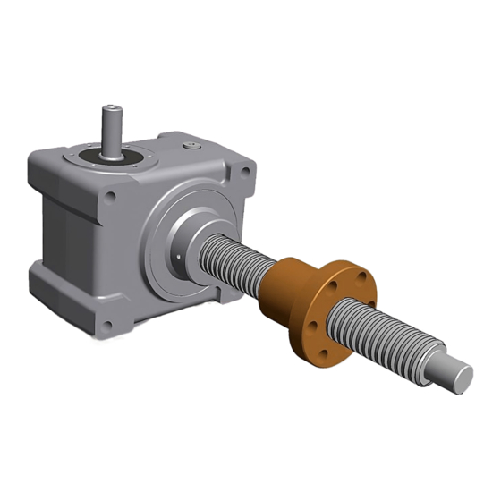
AC motors can be equipped with: • Inverter predisposition • Negative electromagnetic brake (braked if not electrically powered) • 2’ shaft (if there is no negative electromagnetic brake) 2.2 DESCRIPTION OF COMPONENTS AND ACCESSORIES For performance, refer to the product catalog. The following drawing identifies the main parts that make up the screw jack. - Page 32 TECHNICAL SPECIFICATIONS Three-phase 400-830 V/50 Hz Three-phase 390-830 V/60 Hz AC motor Single-phase 190-400 V/50 Hz Single-phase 220-480 V/60 Hz DC motor On request Gear reduction mechanism Worm screw/Worm wheel Linear movement mechanism ACME or ballscrew lead screw and nut Front Ends Rear...
-
Page 33: Motorizations
: for inverter-controlled brake motors, the brake must be applied separately from the motor. NB: when designing the application, it is necessary to define how to handle the transient given by the motor’s acceleration and deceleration ramps. For DC motors, contact MecVel’s technical department. Use and maintenance handbook HT-HR - 33... -
Page 34: Control And Adjustment Of The Screw Jack Stroke
2.2.2 CONTROL AND ADJUSTMENT OF THE SCREW JACK STROKE Different stroke control systems can be applied to screw jacks. In this case, the types of devices available are: • Integrated mechanical limit switches (F) • Magnetic limit switches (FCM) • Inductive limit switches (FCI) •... -
Page 35: Magnetic Limit Switches
2.2.2.3 MAGNETIC LIMIT SWITCHES (FCM) - HT VERSION ONLY To adjust the stroke of the translating screw to a pre-set value, act on the sensors mounted outside the screw jack according to the following procedure: Position the limit switches at opposite ends of the screw jack Retract the screw to the desired closed position ( Place the limit switch FCMC in the reading position (LED on) Tighten the fixing screw of the limit switch FCMC... -
Page 36: Inductive Limit Switches
• REED NO CIRCUIT : circuit with normally open Reed switch protected by varistor against overvoltages generated when the circuit is opened and LED display system • PNP CIRCUIT : Hall effect circuit with PNP output, protected against polarity reversal and overvoltage peaks and LED display system Reed NC circuit Reed NO circuit PNP circuit... -
Page 37: Encoder
To regulate the FCI limit switches position (if adjustable), proceed as follows: 1. Remove the 2 screws “A” 2. Lift the cover “B” 3. Loosen the 2 screws “C” 4. Slide the plate “D” in the two directions until it reaches the desired position 5. -
Page 38: End-Fittings
Potentiometer Adjusting screw POTENTIOMETER FEATURES Performance Version A Version B Max. working angle 340° ± 3° 352° ± 2° Resistance in Ohms 1K/5K/10K (standard) 1K/5K/10K (standard) Recommended voltage 10 V max. 50 V max. Independent linearity ± 2% ± 1% Tolerance ±... -
Page 39: Safety Nut
2.2.5 SAFETY NUT - HR VERSION ONLY The safety nut is an optional device allowing to check the wear of the main nut on which the trapezoidal screw acts. Heavy loads and prolonged use in fact could wear the main nut until the end of the thread on the trapezoidal screw. - Page 40 TRACTION/PULLING LOAD COMPRESSION/PUSHING LOAD Main nut Gap X Safety nut A = Ø reference according to the screw jack size TABLE TO CHECK THE MAIN NUT WEAR Gap X Screw jack Ø A With new Minimum value with Maximum value with size main nut commpression/pushing load...
-
Page 41: Safety Nut Gu
2.2.5.1.3 SAFETY NUT GU This safety nut corresponds to a “supported version” of the safety nut G. The operating mode is the same of the G version, with the addition of an inductive limit switch constantly checking the wear of the main nut. The more the main nut wears, the more the limit switch mounted on the safety nut gets closer to the metal part screwed to the main nut, until the activation of the inductive limit switch itself (for its features, refer to the paragraph on inductive limit... -
Page 42: Transport And Disposal
The safety nut GU is not available with screw jacks working with loads in both directions. 3 TRANSPORT AND DISPOSAL The product is delivered in packaging (cardboard boxes, wooden crates, etc.) depending on the agreement with the customer and on the size of the product itself. -
Page 43: Electrical Connection
The load eccentricity due to incorrect choice of ends and/or incorrect mounting, resulting in misalignment of the fastening points, gives rise to radial loads, resulting in wear of the internal components of the screw jack and irregularities in its operation. The screw jack must work within its nominal stroke, in order to avoid a mechanical stop. -
Page 44: Duties Of The User
The standard duty cycle to which the performance of screw jacks is referred is S3 30% at an environmental reference temperature of -10°C +60°C. Not all MecVel screw jacks are suitable for installation in environments with a potentially explosive atmosphere. In this case, contact MecVel. -
Page 45: Limit Of Use Of Hr Screw Jacks
5.1.1 LIMIT OF USE OF HR SCREW JACKS Screw jacks from HR series must never exceed the buckling factor as shown in the related paragraph. 5.1.1.1 CRITICAL ROTATION SPEED OF THE SCREW The rotation speed of the screw must never exceed the limits shown in the graphs below. -
Page 46: Limit Of Use Of Ht Screw Jacks
5.1.2 LIMIT OF USE OF HT SCREW JACKS Screw jacks from HR series must never exceed the buckling factor as shown in the related paragraph. 5.1.3 PERMISSIBLE BUCKLING FACTORS Screw jacks from HR series, according to the kind of fixing of the gear box and the nut, and screw jacks from HT series, according to the kind of fixing of the gear box and the front end, must comply with the ratio between max. -
Page 47: Preparation Of Working And Duty Cycles
MOUNTING WITH BOTH GEAR BOX AND NUT/FRONT END BOUNDED (EULER III) 1000 Screw length [m] 5.2 PREPARATION OF WORKING AND DUTY CYCLES Before starting the duty cycle, it is necessary to check: • The correct installation of the screw jack •... -
Page 48: Handwheel For Manual Driving
In any case, it is forbidden to start the screw jack until the machine for which it is intended has been declared in compliance with the relevant EU Directives. 5.3.1 HANDWHEEL FOR MANUAL DRIVING Screw jacks can be equipped with a handwheel for manual operations. The handwheel can be placed at the rear of the motor or on the gear box housing, sideways (see below). -
Page 49: Screw Jack Maintenance
For single-phase motors, never connect the MS safety limit switch directly to the motor conductor. Before to run the screw jack, as required by the Machinery Directive 2006/42/EC, it is mandatory that the correct risk assessment is carried out and all the necessary actions performed. -
Page 50: Screw Jack Maintenance Operations
Checking the correct passage of cables through cable glands * illustrative image 6.3 REPAIRING THE SCREW JACK In the event of faults, do not attempt to repair the screw jack yourself, but contact MecVel technical support for the necessary instructions. 50 - Use and maintenance handbook HT-HR... -
Page 51: Replacing The Screw Jack
7 WARRANTY CONDITIONS For general sale and warranty conditions, refer to MecVel catalog or to www.mecvel.com. 8 NOTES Special notes on use and maintenance of these screw jacks are available only for special configurations. - Page 52 MecVel Srl = m(e)c(vel) Via Due Portoni, 23 40132 Bologna - Italy T . +39 051 4143711 The formula to automate your info@mecvel.com linear motion with the best energy www.mecvel.com...
Need help?
Do you have a question about the HT-HR Series and is the answer not in the manual?
Questions and answers