
Related Manuals for Kaye Validator AVS


Summary of Contents for Kaye Validator AVS
- Page 1 Validation ® Kaye Validator User’s Manual Amphenol M5100-EN Rev. D October 2016 Advanced Sensors...
- Page 2 [No content intended for this page]...
- Page 3 ® Kaye Validator Thermal Process Validation System User’s Manual M5100-EN Rev. D October 2016 Copyright © 2016 Amphenol Thermometrics, Inc. Amphenol 967 Windfall Road St. Marys, PA 15857-3333, USA Advanced Sensors Web: www.amphenol-sensors.com.
- Page 4 [No content intended for this page]...
-
Page 5: Table Of Contents
The Kaye Validator AVS .............. 1 Chapter 1. Introduction ....................1 Validator AVS Benefits ................. 3 About this Manual ..................5 The Kaye Validator AVS System ..............6 The Validator AVS Hardware .............. 6 1.4.1 Sensor Input Modules (SIMs) .............. 7 1.4.2 Plug-In Hardware Connections ............ - Page 6 Kaye IRTD ....................31 Temperature Reference ................32 Sensor and IRTD Installation ............33 2.5.1 Connecting the System ................35 Setting the Validator AVS Time and Date ..........36 Preventive Maintenance ................36 Fuse Replacement ................36 2.8.1 Calibration .................... 36 2.8.2...
- Page 7 Specifying Group Calculations ..............72 Specifying Calibration Parameters ............73 Specifying Qualification Study Conditions ..........75 Reviewing and Changing the Setup ............76 6.10 Calibrating and Verifying Sensors ........... 77 Chapter 7. Introduction ....................77 Kaye Validator AVS User’s Manual...
- Page 8 Contents Loading a Setup into the Validator AVS ..........79 Selecting Sensors ..................80 Calibrating or Verifying Sensors ..............81 Automatic, Semi-Automatic or Manual Mode ........82 7.4.1 Calculate Stability ................82 7.4.2 Calculate Deviation of Uncalibrated Sensors ........83 7.4.3...
- Page 9 The Graph Report Screen ..............125 10.11 The Customize Calculations Screen ..........128 10.12 The Customize Groups Screen ............129 10.13 Report Options Screen................130 10.14 Appendix A. Understanding Audit Trail Events ......... 132 Appendix B. Environmental Compliance ............. 142 Kaye Validator AVS User’s Manual...
- Page 10 The Risks and Your Role in Reducing Them ........ 145 B.2.2 B.2.3. System Specifications ................146 FCC Part 15 details .................. 147 Appendix C. Safety and Precautions ............148 Appendix D. Service information ..............150 Kaye Validator AVS User’s Manual...
-
Page 12: Chapter 1. The Kaye Validator Avs
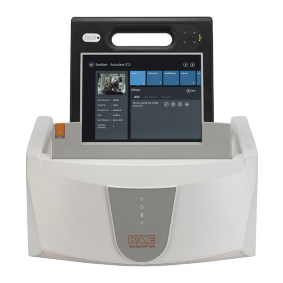
The Kaye Validator AVS 1.1 Introduction Figure 1: The Kaye Validator AVS The Kaye Validator® AVS system is a validation system designed for thermal process validation in the pharmaceutical and biotechnology industries. It features automated sensor calibration and qualification reporting. - Page 13 Assets, Studies, and Qualification data are visible across all Consoles. While a Console can log in to one Validator at a time, multiple Consoles can log in to the same Validator AVS. Users can disconnect a Console after initiating a study or qualification; also, any user with any Console can stop a calibration or study currently running on any Validator AVS.
-
Page 14: Validator Avs Benefits
Validator AVS Benefits A Kaye Validator AVS system consists of the Validator AVS and the Validation Console. The console can be docked directly to the Validator AVS and is used as the operator interface to the Validator AVS. Selectable input capacity (1 to 4 SIMs) up to 48 total inputs. - Page 15 Chapter 1. The Kaye Validator AVS Sensor Inputs • Up to 4 SIMS: 48 channel capacity • Scan speed of 36 channels per second / 48 channels 2 seconds • SIMs for TCs, 4-20mA, 0-10V and RTDs • Improved Sensor Connectivity (quick-fix & lock connectors) •...
-
Page 16: About This Manual
The first part of this manual provides an overview of the Validator AVS hardware, instructions for creating user accounts and entering asset and equipment information, and an overview on using the Validator AVS software. The second part of this manual covers using the Validator AVS, including calibrating sensors, running qualification studies, and verifying sensor calibration. -
Page 17: The Kaye Validator Avs System
Figure 2: The Validator AVS System The Validator AVS accepts up to 48 inputs in any combination of thermocouple, voltage or current inputs or 24 RTD inputs. The instrument is equipped with an universal power supply... -
Page 18: Sensor Input Modules (Sims)
Chapter 1. The Kaye Validator AVS 1.4.2 Sensor Input Modules (SIMs) The Validator AVS uses Sensor Input Modules to provide secure connection of sensors to the Validator AVS while protecting the electronics from draft, dust, humidity, electrical noise and mechanical shock. SIMs are designed to be wired once and used repeatedly. -
Page 19: Plug-In Hardware Connections
Chapter 1. The Kaye Validator AVS 1.4.3 Plug-In Hardware Connections The Validator AVS has connectors on the back of the unit for easy plug-in of SIMs, temperature standards, temperature references. It also provides connection ports for USB and Ethernet for the Console and the Validator. Another separate USB port is utilized for the year device calibration USB with the ICAL software. -
Page 20: The Validator Avs Software
1.5.1 User Access You can set user access to the Validator AVS to match the way your company works. The Validator AVS software is designed user level has specific permissions that define system access. -
Page 21: Electronic Data Requirements
Chapter 1. The Kaye Validator AVS 1.5.3 Electronic Data Requirements The Validator AVS is designed to help you meet the guidelines for electronic signatures as specified in FDA Regulation 21 CFR part 11, Electronic Records; Electronic Signatures. • Two levels of identification - user ID and password •... -
Page 22: Sensor Calibration
After you have created and saved your setup, you run the study by loading the setup into the Validator AVS via connection from your Console to the Validator AVS. See the Validator AVS online Help for instructions on setting up a study. -
Page 23: The Qualification Study
During a qualification study, the Validator AVS performs calculations and compiles data for your reports. For details how to run the qualification study using the Validator AVS software, see Chapter 9, The Qualification Study and the Validator AVS online Help. -
Page 24: Using The Validator Avs System
Once the hardware is connected, use the Validator AVS software to display a graphical representation of your validation equipment to verify hardware and communications connections. 6. Load the setup into the Validator AVS to calibrate sensors and run your study. During sensor calibration and the qualification study, you can use the IMPORTANT: Console to view data and track your progress. - Page 25 Chapter 1. The Kaye Validator AVS 1.6 Using the Validator AVS System (cont.) The Validator AVS collects all study data and stores it in a secure data file internally. When the study is finished the data is downloaded into your Console’s memory.
-
Page 26: Chapter 2. The Validator Avs Hardware
The Validator AVS Hardware 2.1 Introduction The Kaye Validator AVS comes equipped with a universal power supply, a power cord for 115 VAC (or 230 VAC as necessary), over 4 GB of internal memory, and a USB flash drive interface. This chapter describes the Validator hardware and provides instructions for connecting the system. -
Page 27: The Validator Avs Instrument
AC power. 2.2.1 Connection Ports The back of the Validator AVS (shown in Figure 5 below) has ports for electrical and communication connections. Each connection port is labeled with an icon representing its function. The connection ports are defined on page 18. Below the ports are the ON/OFF switch and the AC power input. -
Page 28: Symbol Identification
ICAL device. ICAL port is used for Service only USB/ Ethernet Connector There are two USB/Ethernet communications ports for connecting the Validator AVS and the Console. Ethernet cable to be less than 3 meters long 2.2.2 Symbol Identification Protective Earth Terminal Caution (Refer to accompanying documentation.) -
Page 29: Side Port For Data Transfer
Chapter 2. The Validator AVS Hardware 2.2.3 Side Port for Data Transfer On its left side, the Validator AVS offers a side port with a USB port (to accommodate a USB flash drive) and a button for data transfer, as shown in Figure below. -
Page 30: The Console
2.2.4 The Console For programming and control, each Validator AVS includes a Microsoft Industrial Embedded OS based Console Figure below shows the procedure for docking a Console to a Validator AVS via its docking station. Figure 7: Docking and Releasing Console... -
Page 31: Internal Memory
Kaye technician for emergency recovery. The Validator AVS allows you to scan data at 12 inputs per second per SIM slot during the qualification study. If SIM slot 4 is used the storage rate is reduced to 2 seconds allowing the maximum of 36 inputs per second or 48 inputs every 2 seconds. -
Page 32: Backup Battery
IMPORTANT: In the event of power glitches or short-term drops in supply voltage (“brownouts”), there is a remote chance that the Validator AVS will fail to fall back to its backup battery. In this case the Validator AVS will reset and potentially lose any study data stored in internal memory. -
Page 33: Sensor Input Modules
Chapter 2. The Validator AVS Hardware Sensor Input Modules The Validator AVS plug-in Sensor Input Modules (SIMs) help reduce the time it takes to perform validation studies. Each SIM has: • 12 sensor input connections, 6 for RTD SIMs •... -
Page 34: Wiring Sims
Chapter 2. The Validator AVS Hardware 2.3.1 Wiring SIMs There are two methods for wiring SIMs. You can assign sensor locations in your setup file, and then wire the sensors according to the Setup Report, or you can buy pre-wired SIMs or wire the SIMs yourself and then create a setup that reflects the sensor locations. - Page 35 3 = Drain hole 7. Tighten the two screws in the top of the module to close the SIM. 8. Label the SIM with SIM slot number, SIM serial number, the Validator AVS serial number, and the calibration date. Note: To wire the dedicated 4-20 mA SIM, see document Z2036, “4 to 20 mA Sensor Input Module.”...
- Page 36 Chapter 2. The Validator AVS Hardware 2.3.1a Connecting a Thermocouple Connect types J, K and T thermocouples to the connectors as shown in Figure 10 below. Cut through the outer insulation to separate the red and blue wires, and then strip back each wire approximately ½...
- Page 37 Chapter 2. The Validator AVS Hardware 2.3.1a Connecting a Thermocouple (cont.) Also, it is recommended to shave open about 1/4 inch from each of the red and blue inner wire jackets at opposite ends of the outer insulation drip cut to allow condensate drainage from within the individual wires, as shown in Figure 12 below.
- Page 38 Chapter 2. The Validator AVS Hardware 2.3.1b Connecting a Contact You can connect dry contact inputs directly to the TC-SIM, as shown in Figure 13 below. Dry contact inputs can be used to make a time notation in the data file (to mark start exposure, stop exposure, start of qualification, end of qualification) and to mark any events that occur during the qualification study.
- Page 39 Chapter 2. The Validator AVS Hardware 2.3.1d Connecting a Current Transmitter A dedicated 4-20 mA SIM is available that provides 12 current inputs and a connection for an external power supply. However, a current transmitter can also be connected to the standard TC-SIM. Connect a precision shunt resistor to the connectors to convert the current to a measurable voltage, as shown in Figure 15 below.
- Page 40 Chapter 2. The Validator AVS Hardware If the sensor requires More Than 4mA, it will normally have a second set of terminals to supply power. • Connect the transmitter output to the input channel (+ to + and - to -), as shown in Figure 2.
-
Page 41: Kaye Irtd
01. The Validator AVS communicates with IRTD probes with addresses 01 or 02. However, if both IRTD probes are set to 01, the system displays a communications error. The Validator AVS also reports a communications error if an IRTD is disconnected from the unit during sensor calibration or a qualification study. -
Page 42: Temperature Reference
Temperature references provide the stable temperature required for sensor calibration. Six temperature reference models are available. They are designed to provide different temperature ranges and are compatible with the Validator AVS. LTR-90 (setpoint range -95°C to 140°C at 23°C ambient) Recommended for calibration of sensors used in freeze dryers, freezers, cryogenic units, incubators and steam autoclaves. -
Page 43: Sensor And Irtd Installation
The Kaye LTR-90, LTR -25/140, LTR -40/140, and the HTR 400 temperature references have inserts for thermocouples and two Kaye IRTDs. Failure to use these inserts to achieve proper thermocouple placement in the temperature reference will result in reduced accuracy during calibration. - Page 44 Chapter 2. The Validator AVS Hardware 2.5.1 Sensor and IRTD Installation (cont.) CTR -80 To insert thermocouple sensors into the CTR -80: • Loosen the sliding clamp mechanism on a thermocouple well, insert the thermocouple sensors 7.5 inches into the well, slide the clamp into place, and tighten the clamp to hold the sensors in place.
-
Page 45: Connecting The System
Chapter 2. The Validator AVS Hardware 2.6 Connecting the System All system connections are on the back of the Validator AVS. Make sure the unit is powered off before connecting the IRTD, temperature reference (LTR-90, LTR -25/140, LTR -40/140, HTR 400, CTR -80, or CTR -40), and SIMs To connect your Validator AVS, complete the following steps: 1. -
Page 46: Setting The Validator Avs Time And Date
Preventive Maintenance 2.8.1 Fuse Replacement The Validator AVS is equipped with a 250V T 4A fuse. The fuse is located in the line filter along with the power cord. To replace the fuse: Turn the power off. Disconnect the power cord from the line filter. -
Page 47: Transporting And Shipping
Chapter 2. The Validator AVS Hardware Transporting and Shipping The Validator AVS is designed to be easily transportable from one place to another within a plant. The unit weighs approximately 26.5 pounds (lb) or 12 kg, including the Validation console (without SIMs) and comes with two robust handles for carrying. -
Page 48: Chapter 3. Creating User Accounts
Chapter 3. Creating User Accounts 3.1 Introduction The Kaye Validator AVS software Password Maintenance utility allows a user with System Administrator permission to create and maintain user accounts, set site options, backup and restore user information, and view, print, and maintain the audit trail. All system administration tasks are accomplished through the Password Maintenance utility program and logged in the audit trail. - Page 49 3.2 Logging in as a Default System Administrator The Kaye validation console boots automatically into the Kaye Operator windows account on startup. In the start menu, you can start the Kaye Validator AVS software or use Kaye legacy software (Administrator password required!).
- Page 50 3. Enter your password again in the Confirm password field and press OK. At this point you should record your user ID and password for future reference. You need both to log in to the Validator AVS. If you do not enter the correct user ID/password combination, you will be denied access.
-
Page 51: Creating New System Administrator Accounts
1. Press the Admin pane on the main screen. The Admin Settings window opens at the Preferences tab. 2. From the Admin Settings window, press User Management. 3. On the User Management screen, press New User, and enter your name in the Name text box. Kaye Validator AVS User’s Manual... - Page 52 6. Enter your password again in the Confirm password field and press OK. At this point you should record your user ID and password for future reference. You need both to log in to the Validator AVS. If you do not enter the correct user ID/password combination, you will be denied access.
-
Page 53: Creating New User Accounts
The User Management screen displays the list of active users. The System Administrator accounts you just created is the only name on the list (the default System Administrator account Kaye has been deleted). Now you are ready to add users to the system. 3.3 Creating New User Accounts When you create a new user account, the user name is added to the active user list. - Page 54 • Changes system preferences • Creates or modifies a setup • Changes the setup stored in the Kaye Validator AVS • Calibrates sensors or verifies sensor calibration • Manually stops sensor calibration or calibration verification •...
- Page 55 In case there is no known Administrator access anymore to the system possible Kaye can provide a one-time Emergency access with the sole purpose to add a new Administrator account.
-
Page 56: Setting Preferences
3.4 Setting Preferences Figure 24: Preferences Tab in the Admin Menu The Kaye Validator AVS software installs with default system settings. You can change any or all of the settings on the Preferences screen. The new settings become effective independently. - Page 57 4. Press the 60 Hertz or 50 Hertz radio button to set the line frequency. Choose the setting that matches your environment. IMPORTANT: The aye Validator AVS filters noise induced by the AC Power in order to achieve its high accuracy performance. If the line frequency is not set correctly, the filter is not working correctly resulting in a higher signal noise level.
-
Page 58: Setting Policies
3.5 Setting Policies Figure 25: The Policies Tab The Kaye Validator AVS software allows you to set policies that give users more flexibility how to handle the password system, lethality D-Value and the calibration warning. As the System Administrator you can adjust policies that: •... -
Page 59: Updating The Kaye Validator Avs Firmware
Updating the Kaye Validator AVS Firmware Figure 26: The Firmware Upgrade Tab A new firmware release upgrade release for the Kaye Validator AVS can be applied using the AVS Firmware Upgrade tool from the Admin functions. For upgrading the Firmware please follow the steps exactly as outlined in the software: 1. -
Page 60: Handling Data Files
Chapter 3. Creating User Accounts 2. Insert a USB thumb drive with the firmware provided by Kaye into the USB port of the Kaye console on the backside of the Validator AVS. You can easily identify the correct USB port by referring to the displayed picture. - Page 61 Data selection there’s a date filter to prevent old data to be copied to the console. The date filter specifies a time frame with simple dropdown selection. The copied data is merged with the existing console data. Figure 28: Sync In - Date Filter Kaye Validator AVS User’s Manual...
- Page 62 Figure 30: AVS Convert – Import comments Note: Imported Validator 2000 files are not available under an Asset but in the report tool under the tile “Others”. Kaye Validator AVS User’s Manual...
-
Page 63: Online Help
“Windows Help” and “Help”. While “Windows Help” shows the help screen of the operating system, the “Help” button displays context-specific help for that AVS application specific screen. Kaye Validator AVS User’s Manual... -
Page 64: Chapter 4. Defining Equipment
Calibration reminder based on the calibration reminder setting in the preferences and the calibration due date. Search study files where a particular Kaye equipment was used. The search bases on the entered serial ID of the Kaye equipment and the automatically retrieved serial numbers saved within the study files. -
Page 65: Adding New Equipment
Chapter 4. Defining Equipment 4.1 Adding New Equipment To add a new piece of Kaye equipment to your Kaye Validator AVS system, press the plus (+) icon on Equipment Hub screen. The New Equipment screen opens. Figure 32: New Equipment Screen You enter details separately for each new piece of equipment. -
Page 66: Checking Details For Existing Equipment
Chapter 4. Defining Equipment Checking Details for Existing Equipment To review the details for a particular piece of Kaye equipment press the tile for that particular item on the Equipment Hub screen. The Equipment Details screen opens. Figure 33: The Equipment Details Screen On the left side of the screen the details as follows are listed: •... -
Page 67: The Calibration Reminder
When opening the Equipment the tiles for equipment due for calibration will be displayed enlarged in light blue and showing the calibration due date directly within the tile. When the equipment is recalibrated the user needs to update the calibration data and the calibration due date manually. Kaye Validator AVS User’s Manual... -
Page 68: Chapter 5. Defining Assets
To open the Assets Hub, press the Assets tile on Main Menu. The Assets Hub appears similar to Figure below. Figure 34: The Assets Hub The Asset Hub screen lists the various assets validated by your Kaye Validator AVS system. On the top text line, you can click on the category to display the assets by: •... -
Page 69: The Asset Details Screen
In the upper left, the title will be the type and name of the asset. The pane on the left displays up to three user-loaded photos (swipe to change to the next picture) of the asset, and lists the asset information as entered by the user with following data: Kaye Validator AVS User’s Manual... - Page 70 With the “Copy to drive” button it is possible to copy the selected setup file to a chosen folder. With the new Kaye Validator AVS system it is not necessary anymore to transfer setups via an USB thumb drive anymore. The functionally is purely for possible support analysis by the Kaye support that might request a setup file from the operator for analysis of issues with a study run.
-
Page 71: The New Asset Screen
SOPs or calibration certificates.. The New Asset Screen To enter a new asset into the Validator AVS system, go to the Asset Hub screen and press the plus (+) icon. The New Asset screen opens. Figure 36: New Asset Screen... - Page 72 Asset Details screen, as well as a wiring overlay images that provides users of sensor placement on the asset. When you have finished, press Save to save the entry and return to the Asset Hub, or Cancel to leave the screen without changes. Kaye Validator AVS User’s Manual...
-
Page 73: Chapter 6. Defining Study Setups
Chapter 6. Defining Study Setups Chapter 6. Defining Study Setups Before you can run a qualification study, you must use the Kaye Validator AVS software to create or modify a setup. A setup defines everything required to calibrate sensors and run a qualification study. -
Page 74: Create A Setup File
The setup files for a specific asset are listed on the Setup screen. To modify an existing setup file: • From the Setup Hub screen for your asset, select the setup file that you want to modify You must have user permissions to modify a setup. Kaye Validator AVS User’s Manual... -
Page 75: The Define Setup Screen
EQ ID, Load Description and SOP fields can also accept special characters (hyphen, underscore, forward and backward slash.) When you have completed entering asset data, press the Sensors Configuration button at the upper right to continue. Kaye Validator AVS User’s Manual... -
Page 76: The Sensors Configuration Screen
SIM, press Select, and those sensors all appear as selected on the left pane. To deselect a sensor, press on the individual sensor, or select a range of previously selected sensors on the Select Sensors pane, and press Select. Kaye Validator AVS User’s Manual... - Page 77 • Thermocouple (Sub Types) J, K, T, E, B, R, S, N • Voltage • Current • Pressure (V or mA) • Contacts (Open/close, On/Off, 1/0). • RTD (PT100, 4-Wire) Kaye Validator AVS User’s Manual...
- Page 78 In the last step the sensor input is marked with a Description sensor label number, and to enable/disable auto numbering. Auto numbering is enabled only if more than one sensor is selected. After the sensor configuration pressing the Group Sensors tab to the right advances to the next screen. Kaye Validator AVS User’s Manual...
-
Page 79: Understanding Groups
Chapter 6. Defining Study Setups 6.5 Understanding Groups Grouping is a key concept of the Kaye Validator AVS software. After your qualification study is complete, grouping allows you to customize your reports. Use the following guidelines when defining groups: •... -
Page 80: Assigning Sensors To Groups
The Group name text box should allow characters that can be upper and lower case, numerics, special character like hyphen, underscore, slash (forward and backward) and blank. Enter the name, and toggle the save button to save the group. Kaye Validator AVS User’s Manual... - Page 81 The printer button enables the export of the wiring overly to a pdf file that can be uploaded to the asset with the upload document function in the asset details. When you have finished and saved your changes, press Calculations to proceed to the Group Calculations screen. Kaye Validator AVS User’s Manual...
-
Page 82: Specifying Group Calculations
It is also possible to define events to monitor during the study. These events are listed in the reports and can be imported into the define cycles screen of the reporting tool. When finished, press Calibration Parameters to enter the qualification parameters. Kaye Validator AVS User’s Manual... -
Page 83: Specifying Calibration Parameters
6.8 Specifying Calibration Parameters Figure 44: Calibration Parameters Screen The Kaye Validator AVS provides both sensor calibration and calibration verification. Before performing a qualification study, calibrate the temperature sensors to correct raw temperature readings to a NIST-traceable temperature standard. During calibration the Kaye... - Page 84 Deviation criteria for uncalibrated temperature sensors, and deviation criteria for calibrated temperature sensors over a fixed time period. Deviation is the difference in temperature between the sensor values and the temperature standard. Kaye Validator AVS User’s Manual...
-
Page 85: Specifying Qualification Study Conditions
Data storage options - the rates at which data is written to disk during a qualification run • Output relay - the events that activate the two independent output relay When you have finished, press Review to check your entries and save the setup. Kaye Validator AVS User’s Manual... -
Page 86: Reviewing And Changing The Setup
Asset Details • Sensor Details • Calculation • Groups • Report Header • Calibration Parameters • Qualification Parameters Press Save to save the setup, or use the back button to exit the Setup menu without changes Kaye Validator AVS User’s Manual... -
Page 87: Chapter 7. Calibrating And Verifying Sensors
With the Kaye Validator AVS, you calibrate sensors at a low setpoint and a high setpoint. When you start calibration, the Kaye Validator AVS computes the stability of the temperature sensors and the temperature standard at the specified setpoint, according to the parameters defined in your setup. - Page 88 Chapter 7. Calibrating and Verifying Sensors The Kaye Validator AVS repeats this process for both setpoints. You can also specify a check point in your setup. During check point, the Kaye Validator AVS calculates and logs deviation on the calibrated sensors.
-
Page 89: Loading A Setup Into The Validator Avs
7.2 Loading a Setup into the Validator AVS Before you begin the calibration or calibration verification process, you have to load your setup into the Kaye Validator AVS. If a Kaye IRTD is used then connect Kaye IRTD to top port of the Validator AVS. -
Page 90: Selecting Sensors
Initiate Verification to perform a verification. (Press Cancel to discard the sensor selections and return to a fresh screen. Press the return button in the upper left to exit the option.) Note: Once you begin a new calibration, any offsets from previous calibrations will be lost. Kaye Validator AVS User’s Manual... -
Page 91: Calibrating Or Verifying Sensors
IRTD before starting the study. Figure 48: Calibration Study Screen The Kaye Validator AVS clears calibration offsets stored in the SIMs for the selected sensors, and establishes communications with the temperature reference and the IRTD. The Calibration screen displays the temperature readings and stability readings for each sensor being... -
Page 92: Automatic, Semi-Automatic Or Manual Mode
7.4.1 Automatic, Semi-Automatic or Manual Mode When you start calibration, the Kaye Validator AVS software detects whether or not a Kaye temperature reference and an IRTD are connected. Both are required for fully automatic operation. If either the Kaye temperature reference or the IRTD is not found calibration verification switches to semi-automatic mode. -
Page 93: Calculate Deviation Of Uncalibrated Sensors
7.4.3 Calculate Deviation of Uncalibrated Sensors When the IRTD and all sensors reach stability, the Kaye Validator AVS calculates deviation by comparing each uncalibrated sensor to the IRTD, and then logs the stability and uncalibrated deviation data to the calibration report file. The Kaye Validator AVS marks any sensor outside the deviation criteria as failed. -
Page 94: The Graph View
7.5 Current Calibration and Hardware Connections Both List and Graph views display essential data: Bath serial number Hardware Connection status Kaye Validator AVS User’s Manual... -
Page 95: Reasons For Calibration Failure
Failed uncalibrated deviation • Failed calibration due to Unstable IRTD and loggers • Failed calibration due to not enough data Data for a live calibration or verification refreshes every 5 or 10 seconds as per display rate. Kaye Validator AVS User’s Manual... -
Page 96: Chapter 8. Viewing Live Data
Validator AVS window. Figure 50: Main Menu with Hardware Discover Tile The easiest way to connect to a Validator AVS is to dock the Validation console into the docking port of the Validator AVS. The Docking Connection is represented by the preselected orange “USB/Docking”... - Page 97 Figure 51: Select Validator AVS Screen Note: In case a Validator AVS is not in the same IP segment the discover function will not find it. Nonetheless if the TCPIP address of the Validator is known and the connection not blocked the connection can be established by entering the IP address and adding the Validator AVS to the available devices manually.
-
Page 98: Monitoring Live Data
Menu, which now shows the connected status along with a Disconnect option. Figure 52: Main Menu with Events Tile Figure 53: Current Events Screen In the Events connection specific events like SIM or Power-disconnects are listed. Kaye Validator AVS User’s Manual... - Page 99 (sensor & groups definition) is following the last transferred setup (To transfer a setup you need to start a study). If the Validator AVS is in monitoring status, you can switch between List and Graph view to see live data from the Validator AVS on the screen.
- Page 100 Chapter 8. Viewing Live Data Monitoring Live Data (cont.) If the Validator AVS is in Qualification status, the live screen displays groups as defined in the study. Figure 56: Qualification Study in List View Figure 57: Qualification Study in Graph View...
- Page 101 Chapter 8. Viewing Live Data 8.2 Monitoring Live Data (cont.) If the Validator AVS is in Calibration or Verification status, the live screen displays groups as defined in the study Figure 58: Calibration List View Screen Kaye Validator AVS User’s Manual...
- Page 102 Figure 59: Calibration in Graph ViewScreen Figure 60: Calibration Parameter screen User can start the Qualification or Calibration from the Asset detail screen. Based on the user rights, user can stop Qualification or Calibration activity. Kaye Validator AVS User’s Manual...
-
Page 103: Check Communications Connections
A Device Not Found status indicates that the hardware is not communicating and may not be connected properly. If the link to the Kaye Validator AVS is not responding, all links will be marked with a grey image of device. -
Page 104: Chapter 9. The Qualification Study
The Qualification Study 9.1 Introduction Once the setup is defined and loaded into the Kaye Validator AVS and the sensors are calibrated everything is ready to run a qualification study. The Kaye Validator AVS uses the qualification parameters defined in the setup to perform the qualification study. - Page 105 Note: In the event of power glitches or short-term drops in supply voltage (“brownouts”), there is a remote chance that the Kaye Validator AVS will fail to fall back to its backup battery. In this case, the Validator could reset and potentially lose any study data stored in internal memory. To prevent this from occurring, Kaye recommends connecting the Validator AVS to an Uninterruptible Power Supply (UPS) in areas likely to experience brownouts.
-
Page 106: Load A Setup
When loading a setup with a different line frequency than the setup currently in memory, the Kaye Validator AVS must stabilize for approximately 2 - 3 minutes before running a qualification study or invalid data is displayed. - Page 107 Select now the Validator AVS to run the study. After pressing the “Discover” button the screen displays all the Validator AVS’ that are available. By default, the screen highlights the Validator AVS that was last used with this particular Console. It is possible to connect the Validator AVS in either of three ways: •...
-
Page 108: Viewing The Active Qualification Study
When viewing sensor readings and calculations, the following guidelines apply: • Calculations are computed, events are monitored and displayed on the Console screen. • The resolution of sensor readings and calculation results is dependent on the lowest resolution in the group. Kaye Validator AVS User’s Manual... - Page 109 After stopping the study the Save Study button becomes available. Please save the study to your console. If a console is connected to a Kaye Validator AVS with an unread study it will insist on reading the study before starting any new study.
-
Page 110: Graph Real-Time Sensor Readings And Calculations
To graph real-time sensor readings and calculations: Press the Graph View option. The Graphs screen displays. All the available Groups in that particular setup are displayed, when pressing the button for each group, the corresponding graph is displayed. Kaye Validator AVS User’s Manual... - Page 111 Qualification and Exposure. Figure 66: Hardware Screen On the hardware screen all available hardware connected to the AVS is available including serial numbers and calibration dates. In addition the Sensor Offsets can be reviewed. Kaye Validator AVS User’s Manual...
-
Page 112: Chapter 10. Generating Reports
All reports are generated from secure data files that can only be read by the Kaye Validator AVS software. Reports are not saved; you create reports each time from the secure data files. If a secure data file is tampered with, it is no longer readable by the software and you will not be able to generate reports. -
Page 113: Report Types
The Setup Report can be generated directly from the setup review page or using the reporting tool. • When you generate this report independent of the full study, you can use the Setup Report to check your setup configuration and/or as a guide for wiring SIMs. Kaye Validator AVS User’s Manual... -
Page 114: Calibration Report
The report header lists the date and time the report was printed, and identifies the name of the setup used to calibrate the sensors, your company name, the Kaye Validator AVS serial number, and the firmware and software version numbers. - Page 115 These are the events that are common to all groups: • Start/Stop Qualification • Start/Stop Exposure The second part of this section documents event timer intervals added during post- qualification reporting. Kaye Validator AVS User’s Manual...
-
Page 116: Calibration Verification Report
The report header lists the date and time the report was printed, the setup name, your company name, the name of the person who performed the qualification study, the run number, the Kaye Validator AVS serial number, and the firmware and software version numbers. -
Page 117: Audit Trail
Chapter 10. Generating Reports Validator AVS Audit Trail The Kaye Validator AVS audit trail provides a complete listing of events that affect the integrity of the Kaye Validator AVS PC program and the Kaye Validator AVS instrument. Audit trail events are stored in secure data files to help you meet 21 CFR Part 11 requirements. - Page 118 1 to 96 - Sensor ID 97 - EventCond_MaxMinusAvg 98 - EventCond_MinMinusAvg 99 - EventCond_MaxValue 100 - EventCond_MinValue Audit Events EVENT_PROGRAM_START, EVENT_PROGRAM_CLOSE, EVENT_HMI_CONNECT, EVENT_HMI_DISCONNECT, EVENT_SIM_CONNECT, EVENT_SIM_DISCONNECT, EVENT_IRTD_CONNECT, EVENT_IRTD_DISCONNECT, EVENT_BATH_CONNECT, EVENT_BATH_DISCONNECT, EVENT_THUMBDRIVE_CONNECT, EVENT_THUMBDRIVE_DISCONNECT, EVENT_AC_POWER_FAILURE, EVENT_AC_POWER_RESTORATION, EVENT_POWER_FROM_BATTERY EVENT_BATTERY_AT_THRESHOLD, EVENT_BATTERY_LOW, Kaye Validator AVS User’s Manual...
- Page 119 Table 3: Audit Trail Events (Continued) EVENT_VALIDATOR_SHUTDOWN_DUE_TO_LOW_BATTERY, EVENT_BATTERY_CHARGING_STARTED, EVENT_BATTERY_CHARGING_STOPPED, EVENT_FAN_FAULT,//2 fans EVENT_SETUP_UPDATED, EVENT_AUTO_QUAL_STARTED, EVENT_AUTO_QUAL_STOPPED, EVENT_MANUAL_QUAL_STARTED, EVENT_MANUAL_QUAL_STOPPED EVENT_AUTO_EXPOSURE_STARTED, EVENT_AUTO_EXPOSURE_STOPPED, EVENT_MANUAL_EXPOSURE_STARTED, EVENT_MANUAL_EXPOSURE_STOPPED, EVENT_AUTO_SENSOR_CAL_STARTED, EVENT_AUTO_SENSOR_CAL_DONE, EVENT_MANUAL_SENSOR_CAL_STARTED, EVENT_MANUAL_SENSOR_CAL_DONE, EVENT_MANUAL_SENSOR_CAL_TERMINATED, EVENT_SENSOR_CAL_VERIFICATION_STARTED, EVENT_SENSOR_CAL_VERIFICATION_SUCCESS, EVENT_SENSOR_CAL_VERIFICATION_FAILURE, EVENT_INST_CAL_STARTED, EVENT_INST_CAL_DONE, EVENT_INST_CAL_TERMINATED, EVENT_INST_CAL_VERIFICATION_STARTED, EVENT_INST_CAL_VERIFICATION_SUCCESS, EVENT_INST_CAL_VERIFICATION_FAILURE, EVENT_CALIBRATION_OVERDUE, EVENT_STUDY_COPIED_TO_THUMBDRIVE, Kaye Validator AVS User’s Manual...
- Page 120 Chapter 10. Generating Reports Table 3: Audit Trail Events (Continued) EVENT_STUDY_COPIED_TO_HMI, EVENT_OUTPUT_RELAY_ACTIVATED, EVENT_OUTPUT_RELAY_DEACTIVATED, EVENT_SBC_FW_UPGRADE, EVENT_DAQ_FW_UPGRADE, EVENT_POWERBOARD_FW_UPGRADE, EVENT_FILE_CREATION_FAILURE, EVENT_HMI_SUBSCRIPTION_FAILURE, EVENT_AUDIT_LOG_AT_THRESHOLD, EVENT_AUDIT_LOG_FULL, EVENT_AUDIT_LOG_CLEARED, EVENT_AUDIT_LOG_COPIED_TO_HMI, EVENT_TIME_SYNC, EVENT_CONDITION_OCCURED For a further explanation of audit trail events, refer to Appendix A. Kaye Validator AVS User’s Manual...
-
Page 121: The Reports Hub
The Reports Hub enables users to access any report on the Console. To access the Reports Hub, press the Reports icon from the Start page. To study the content of a particular report, press the button for that report. The Report Analysis Screen opens Kaye Validator AVS User’s Manual... -
Page 122: The Report Analysis Screen
You can choose from different types of analyses for a qualification study: • Standard Reporting – summarizes the entire study. • Advanced Analytics – provides a more detailed analysis of the study. Press either Standard Reporting or Advanced Analysis to proceed to the Report Detail Screen. Kaye Validator AVS User’s Manual... -
Page 123: The Reports Details Screen
• Activity – indicates if the report is based on setup, calibration, qualification or calibration verification. • Setup – lists reports by the setup name of the studies. • Date – lists reports by date. Kaye Validator AVS User’s Manual... - Page 124 Graph - navigates to Summary/Advanced Analysis page and ask for Option to Select for unit Temperature Humidity Pressure Contact Voltage Current • Delete – Delete the selected file Figure 70: Report Detail Screen When Standard Reporting is selected Kaye Validator AVS User’s Manual...
- Page 125 Chapter 10. Generating Reports Figure 71: Report Analysis Screen when Advanced Analytics is selected Kaye Validator AVS User’s Manual...
-
Page 126: The Performance Analysis Screen
Synchronize, the data of the merged files appears in graph form in a sequence. When you press Data Sources, the screen displays two panels. The left panel, Add Source, with a More button that displays all other study files. Kaye Validator AVS User’s Manual... - Page 127 Chapter 10. Generating Reports 10.6 The Performance Analysis Screen (cont.) Figure 73: The Performance Analysis Screen Kaye Validator AVS User’s Manual...
- Page 128 Synchronize — Redraws the graphs with a user-defined starting point and the conclusion of the study as the end point. • Superimpose — Superimposes one file on another for comparative analysis. Press the Chart Properties button to edit Graph properties. Press back arrow to return to previous screen Kaye Validator AVS User’s Manual...
-
Page 129: The Standard Reporting Screen
Once you have created templates, this list displays all the templates Note: If all the groups listed are empty, you cannot launch the Next screen until you have assigned sensors to at least one group in the Group pane. Kaye Validator AVS User’s Manual... -
Page 130: The Add Cycles Screen
Chapter 10. Generating Reports 10.9 The Add Cycles Screen Figure 76: The Add Cycles Screen Define the start and end of the qualification cycle using either Cycle selection box option (default) or Time selection box. Kaye Validator AVS User’s Manual... - Page 131 The right check box corresponds to the Qualification End with the timestamp displaying at the bottom left side of the box. The center of the cycle selection box displays the interval period corresponding to Start and End of cycle. Kaye Validator AVS User’s Manual...
- Page 132 All the cycles created above are now displayed under the Show Cycles dropdown list box at Click Unmark Cycle/Unmark Cycles button in Show cycles window to remove the last cycle defined or all cycles at one shot respectively Kaye Validator AVS User’s Manual...
- Page 133 This option deletes from the last cycle to first, end of study and then Start of study. UnMark All will unmark all the cycles, including study start and end. Kaye Validator AVS User’s Manual...
-
Page 134: The Report Screen
2. Customize Groups: we can edit already defined groups and save it for generating graph report and qualification Report. 3. Customize Calculations and modifications in Calculations can be customized and edited. 4. Graph Report: we can generate Graph for defined group and selected Cycle accordingly Kaye Validator AVS User’s Manual... -
Page 135: The Graph Report Screen
Figure 81: Graph Report Screen Depending on the sensor group and graph type selected, you can apply the following calculations: • Max Value • Min Value • Avg and Std Dev • Max-Min • Max-Avg Kaye Validator AVS User’s Manual... - Page 136 • No calculations are available for a contact sensor group. Based on the group selection, the following calculation graphs are generated: • Temperature Sensors • Temperature Sensors Calculations • RH (Humidity) Sensors • RH Sensors Calculations • Pressure Sensors Kaye Validator AVS User’s Manual...
- Page 137 Users can zoom in and out of any graph, or apply the print option to send graphs to a default printer. By default, the graph reports are saved with a unique name, along with the date and timestamp. Header and footer details remain the same as in all other reports. Kaye Validator AVS User’s Manual...
-
Page 138: The Customize Calculations Screen
To specify a calculation. If calculations have already been specified for statistical, lethality or interval calculations a Customize button displays to the left of the calculation label. Press the Customize button to change calculations. When user modifies lethality, interval, saturations calculations values they are applied to generate Report. Kaye Validator AVS User’s Manual... -
Page 139: The Customize Groups Screen
Enter the name, and toggle the button to save the group. The screen also offers different options: • Delete - permits deletion of a sensor group • Move Sensors - permits moving sensors to another sensor group Kaye Validator AVS User’s Manual... -
Page 140: Report Options Screen
First Page, Last Page or All Pages. Note: If you select All Pages, the other selection boxes are not available. Report structure can be customized Kaye Validator AVS User’s Manual... - Page 141 [No content intended for this page]...
-
Page 142: Appendix A. Understanding Audit Trail Events
Appendix A.. Understanding Audit Trail Events Appendix A. Understanding Audit Trail Events All events include the following mandatory data: date and time, user name, user ID, Console ID, Validator ID and Console- Validator ID combination. Table 4: Audit Trail Events Tabulation 1 Users Create a user... - Page 143 Appendix A.. Understanding Audit Trail Events Table 4: Audit Trail Events (Continued) Account Date/time of User account disabled Name of system disabled event administrator User name User ID Account Date/time of User account disabled Automatic Event disabled after event 3 consecutive login failures User name User ID...
- Page 144 Appendix A.. Understanding Audit Trail Events Table 4: Audit Trail Events (Continued) Instrument Calibration Digitizer Date/time of manufacturing event Reference Date/time of manufacturing Voltage event Date/time of manufacturing event Report Files Copy Date/time of Calibration file copied Name of user who Calibration event copied file...
- Page 145 Appendix A.. Understanding Audit Trail Events DRAFT...
- Page 146 Appendix A.. Understanding Audit Trail Events Table 4: Audit Trail Events (Continued) Delete Date/time of Delete qualification file Name of user who qualification event deleted file Setup name User who ran calibration Date calibration started Source directory Destination directory Copy Date/time of Calibration verification Name of user who...
- Page 147 Appendix A.. Understanding Audit Trail Events DRAFT...
- Page 148 Appendix A.. Understanding Audit Trail Events Table 4: Audit Trail Events (Continued) Setup Files Create Date/time of New setup created Name of user who event created setup Setup name User who created Setup Date created Modify Date/time of Setup modified Name of user who event modified setup...
- Page 149 Appendix A.. Understanding Audit Trail Events DRAFT...
- Page 150 Appendix A.. Understanding Audit Trail Events Table 4: Audit Trail Events (Continued) Directory Tampering –restart audit Restart due to Date/time of Automatic Event tampering event trail Directory Back up audit Date/time of backup Name of system trail event administrator Directory Software Date/time of Software version change...
- Page 151 Appendix A.. Understanding Audit Trail Events DRAFT...
-
Page 152: Appendix B. Environmental Compliance
Appendix B. Environmental Compliance Appendix B. Environmental Compliance This appendix contains information on the following topics: • WEEE Directive (see Section B.1) • Battery disposal (see Section B.2) • FCC Part 15 details (see Section B.3) B.1 Waste Electrical and Electronic Equipment (WEEE) Directive The equipment that you bought has required the extraction and use of natural resources for its production. - Page 153 Appendix B. Environmental Compliance DRAFT...
-
Page 154: Battery Disposal
Appendix B. Environmental Compliance B.2 Battery Disposal This product contains a battery that cannot be disposed of as unsorted municipal waste in the European Union. See the product documentation for specific battery information. The battery is marked with this symbol, which may include lettering to indicate cadmium (Cd), lead (Pb), or mercury (Hg). -
Page 155: The Risks And Your Role In Reducing Them
Appendix B. Environmental Compliance B.2.2 The Risks and Your Role in Reducing Them Your participation is an important part of the effort to minimize the impact of batteries and accumulators on the environment and on human health. For proper recycling you can return this product or the batteries or accumulators it contains to your supplier or to a designated collection point. -
Page 156: System Specifications
A summary of the error budget for a validation system after sensor calibration with type T thermocouples, used at steam and dry heat with a Kaye HTR-400 as temperature reference and a Kaye IRTD-400, is listed below. Kaye Validator AVS (resolution and short term stability) 0.017°C... -
Page 157: Fcc Part 15 Details
Appendix B. Environmental Compliance Console Specifications Off (Storage) Temperature 5°C -40°C -20°C -60°C Humidity 8%-90% RH 5%-95% RH Air Pressure 697-1060 hPa 187-1060 hPa Power Supply (ITE) Delta Input : 1.5A, 100-240VAC, 47-63Hz Electronic, SADP-65NB Rev. Output:19V DC, 3.42 A The power supply is compliant with UL-60950-1, CAN/CSA C22.2 No.60950-1, and IEC/EN 60950-1 B.3 FCC Part 15 details... -
Page 158: Appendix C. Safety And Precautions
Appendix C. Safety and Precautions Appendix C. Safety and Precautions Fallowing safety precautions should be taken for proper operation of the unit and to avoid any manual injury To ensure proper air flow, Fans should not be blocked The unit should be serviced by authorized service personnel only. This unit must be opened by Amphenol authorized service technicians only, tempering by unauthorized representatives could void the warranty This unit must be operated under specified environmental conditions only, usage of unit... - Page 159 Appendix C. Safety and Precautions DRAFT...
-
Page 160: Appendix D. Service Information
Appendix D. Service Information Appendix D. Service information We operate a global network of service centres and a field service organization to provide customer support for repair, returns, calibrations, technical support, evaluation and spare parts. Americas Europe China Amphenol Advanced Sensors Amphenol Advanced Sensors Germany Amphenol (Changzhou) Connector 967 Windfall Rd... - Page 161 The language of touch With specific gestures on a touch enabled device, you can quickly perform key activities like Search and Share; there’s a corresponding command for using a mouse or keyboard, so you can interact in whatever way you prefer. Swipe from the right edge for system commands Swiping from the right side of the screen reveals the charms with system commands.
- Page 162 Swipe in and out on the left to bring up previously used apps Swiping in and back out on the left brings up the most recently used apps and you can select an app from that list. Mouse equivalent Place the mouse pointer in the upper left and slide down the left side of the screen to see the most recently used apps Swipe from the bottom or top edge for app commands App commands are revealed by swiping from the bottom or top edge.
- Page 163 Press and hold to learn You can see details when you press and hold. In some cases, pressing and holding opens a menu with more options. Mouse equivalent Point to an item to see more options. Tap to perform an action Tapping something causes an action, such as launching an app or following a link.
- Page 164 Swipe to select Within an app, swipe down or across an item to select it. A quick, short movement works best. On Start, press and hold to select a tile. Mouse equivalent Simply right-click to select within the app. Pinch or stretch to zoom Zooming provides a way to jump to the beginning, end, or a specific location within a list.
- Page 165 Active Qualification Study ......................98 Add Cycles ..........................120 Assets Define ..............................58 Detail ..............................59 Hub ................................. 58 New ................................ 59 Audit trail Events ..............................107 Audit Trail ........................... 107 Battery ............................138 backup ..............................141 Disposal ..............................138 Replacement............................
- Page 166 Index Customize Calculations ............................128 Groups ..............................129 Cycles ............................120 Data Requirement ........................10 Default System Administrator ....................38, 39 Define Setup ..............................63, 65 Defining Equipment ........................54 Detailed Report ..........................104 Deviation Calibrated Sensors ..........................83 Calibration Report ..........................104 Calibration Verification Report ......................
- Page 167 Index Understanding ............................69 IRTD ............................31 Installation .............................. 33 Specification ............................141 Kaye Validator AVS ........................1 Hardware ..............................6 Introduction ............................15 Memory ..............................15 Shipping ..............................37 Time and Date ............................36 Live Data, Viewing ........................86 Maintenance ..........................
- Page 168 Index Performance Analysis Screen ....................116 Policies ............................48 Preferences ..........................46 Qualification ..........................12 Reports ............................102, 104 Start ................................ 96 Study ............................... 94 Viewing ..............................99 Real-Time Graph ..............................100 Sensor Readings ............................. 98 Relay Rating..........................17 Report Analysis Screen ......................112 Semi-Automatic ...........................
- Page 169 Index Default ..............................39 Logging ..............................40 Temperature Reference ....................... 32 CTR ................................. 32 HTR ................................. 32 Installation .............................. 33 LTR ................................32 User Access ..........................9 User accounts Disable ..............................48 User Accounts Creating ..............................43 Voltage Connecting.............................. 28 Waste ............................
- Page 170 [No content intended for this page]...
Need help?
Do you have a question about the Validator AVS and is the answer not in the manual?
Questions and answers