
Related Manuals for Shimpo FGS-VC Series

Summary of Contents for Shimpo FGS-VC Series
- Page 1 97591A FGS-VC Series Motorized Stand Operation Manual Read Manual thoroughly prior to operation. Use instrument only after reading the complete manual. Follow all safety precautions.
- Page 2 Safety Precautions Be sure to read the entire instruction manual thoroughly before initial set-up, operation and maintenance. The instruction manual provides three grades of safety precautions: ”Danger”, “Warning” and “Caution”. Follow these precautions. “Danger” marking indicates possible death, severe injury or fire Danger if the user disregarded.
- Page 3 Attention Safety Warning Pull out the AC outlet for maintenance and check or unusing a long time. Do not plug AC connector into outlet by a wet hand. May cause electric shock, a fire and injury. Attention before using FGS-VC Avoid the following.
-
Page 4: Table Of Contents
Index 1. 1. 1. 1. Ahead of the use Ahead of the use ............................1 Ahead of the use Ahead of the use 1.1. 1.1. 1.1. 1.1. Procedure from the Installation of a force gauge to the measurement Procedure from the Installation of a force gauge to the measurement..........1 Procedure from the Installation of a force gauge to the measurement Procedure from the Installation of a force gauge to the measurement 1.2. -
Page 5: Ahead Of The Use
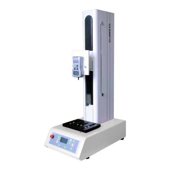
1. Ahead of the use 1.1. Procedure from the Installation of a force gauge to the measurement FGS-VC can measure various loads using Shimpo's digital force gauges which are FGP series and FGP-EX series. Confirm the following procedures before use. - Page 6 2. Names of components Upper limit Knob Force gauge plate Lower limit knob Emergency switch Measurement table Operation panel 3. Names and functions of the operation panel Name Description Emergency stops when pushing. Push the switch when FGS-VC becomes abnormality or hazardous situation at Emergency switch measuring.
-
Page 7: Installation Of Force Gauge
mode. MODE key Use to change operation mode and function setting. SET key The indicated data is set when the key is pushed. START key Start to operate at the program mode. PUSH key Move to the direction of PUSH. STOP key Stop. -
Page 8: Connection To The Force Gauge And The Stand
4.2. Connection to the force gauge and the stand The connection and confirmation between FGS-VC and a force gauge is the following procedure. Parameter setting of the force gauge Set the following parameters. Measurement polarity: + RS232C baud rate: 19,200 bps Refer to the manual of the force gauge. -
Page 9: Operation
4.3. Connection to PC and the stand FGS-VC can connect to PC for taking force and displacement. The software is able to be downloaded from Shimpo's HP free of charge. Refer to the software manual. Cable between FGS-VC and force gauge... - Page 10 Select measurement mode Select Manual, Jog, Single, Continue and Program mode according to the measurement purpose and the usage. Mode can be changed by Mode switch. Start to measure. Start each mode by pressing PUSH, PULL or START switch. Refer to each mode section. FGS-VC is able to test as follows: Compression test Tension test...
-
Page 11: Operation Mode
5.2. Operation mode The operation mode consists of manual and program. The mode is selected by the measurement purpose and the usage. You wish to test by PUSH or PULL key. You wish to test by PUSH or PULL key. You wish to test by PUSH or PULL key. -
Page 12: Manu Mode
5.3. Manual operation mode The manual operation modes are MANU, JOG, SING and CONT mode as follows. The mode is selected by the measurement purpose and the usage. When pressing the PUSH (PULL) key, FGS-VC goes to PUSH (PULL) limit switch position. MANU mode FGS-VC stops if reaching the limit position. - Page 13 Speed Speed can be changed by UP or DOWN button of the SPEED. The speed setting of MANU and JOG mode is common. Also the speed is able to be changed while moving. Display Present position Setting speed Parameter The parameter, which is the speed of MANU and JOG mode, is available while stopping. Pressing SET button, and the speed can be changed by UP or DOWN key of the SPEED.
- Page 14 Parameter The parameter, which is the speed of MANU and JOG mode, is available while stopping. Pressing SET button, and the speed can be changed by UP or DOWN key of the SPEED. Then press SET button for saving. If you want to cancel the setting, press ZERO button. Setting speed The UP or DOWN button of the SPEED can be used to change...
- Page 15 5.3.3. SING mode This mode of operation is ideal for completing one cycle between manual distance limits. The test stand will only operate between the limits that are set by the test stand user. These limits can be either manually adjusted (distance limits).
- Page 16 Speed Speed can be changed by UP or DOWN button of the SPEED. The speed setting of SING and CONT mode is common. Also the speed is able to be changed while moving. Display Present position Setting speed Moving direction Repeat count Setting dwell timer Status of limit switch...
- Page 17 Parameter The parameter, which is the dwell timer and the speed of pull and push, is available while stopping. Pressing SET button, the speed can be changed by UP or DOWN key of the SPEED, the dwell timer can be changed by STOP.
- Page 18 5.3.4. CONT mode This mode of operation is ideal if the user wants the test stand to repeatedly cycle up and down continuously or for a user-programmed number of times. The stand will start in either direction depending on whether PUSH or PULL button is selected.
- Page 19 Speed Speed can be changed by UP or DOWN button of the SPEED. The speed setting of SING and CONT mode is common. Also the speed is able to be changed while moving. Display Present position Setting speed Moving direction Repeat count Setting dwell timer Status of limit switch...
- Page 20 Parameter The parameter, which is the repeat times and the dwell timer and the speed of pull and push, is available while stopping. Pressing SET button, the speed and the repeat times can be changed by UP or DOWN key of the SPEED, the dwell timer can be changed by STOP.
-
Page 21: Prog Mode
5.4. Program operation mode 5.4.1. PROG mode This mode of operation is ideal if user wants the test stand to programmed complex moving. Even if the user does not know the length of the object, the accurate measurement is possible because the function to detect the object to be measured is provided. - Page 22 Display The example of the display under operation is shown below. Detect point Start point Present position Moving direction Operation Start point (Dwell timer) status Setting speed P3 (Dwell timer) Present repeat times status Return to Start point Return to Start point (Dwell timer) - 18 -...
- Page 23 Parameter The parameters are available while stopping. Pressing SET button, the parameter setting starts. The contents of the parameters setting is shown in the below flowchart. Finally press SET button for saving. If you want to cancel the setting, press ZERO button. Force limit The PUSH or PULL button can be used to change.
- Page 24 Moving distance at P1 Point 1 to 5 Previous page The parameter is the distance from "Standard point" to "P1". Moving direction at P1 Also the data should be set as The parameter is the relative coordination. direction of moving from The PUSH or PULL button can “Standard point”...
-
Page 25: Parameter Setting Mode
Force limit The stand controls to give the force less than the "Force limit". If the force limit is detected, the stand will stop immediately. Then the stand executes the next step. Upper limit Start point Standard point Detect point Point 1 Point 5 Point 5... - Page 26 Parameter If you want to cancel the setting, press ZERO button. Sign of Push direction MODE Space means '+'. Saving and go to The UP or DOWN button can be MANU mode used to change. Pressing the button, setting will changed alternately.
-
Page 27: Message Of Status And Error
6. Message of status and error The lower limit was reached. If the status is abnormal, move the “PUSH LMT” is blinking. lower limit switch position. The upper limit was reached. If the status is abnormal, move the “PULL LMT” is blinking. upper limit switch position. - Page 28 Procedure of the initialization of the parameters 1. Turn off, wait one minute. 2. Press ZERO and SET button both, turn on in keeping to press these buttons. 7. Dimensions Upper limit 4.72 Force gauge: FGP, FGPX Lower limit Emergency switch 3.94 Operation panel 2.95...
- Page 29 5.51 5.91 3.94 M8 [mm] M6 [mm] 1.97 0.39-1.26UNF 1.57 3-0.22 M10 [mm] 2-0.35 0.79 4-0.18 1.77 0.79 0.79 Table FGS-100/250VC Plate FGS-100VC Table 5.91 1.77 adjustable 1.77 adjustable [inch] Table Adjust FGS-100/250VC - 25 -...
- Page 30 Upper limit Force gauge: 4.72 FGPX-250H Force gauge Lower limit Emergency switch 3.94 Operation panel 2.95 2.95 11.81 19.69 FGS-250VC [inch] 3.54 2.76 0.20 0.28 Plate FGS-250VC - 26 -...
-
Page 31: Troubleshooting
FGPX-0.2 to FGPX-100 FGPX-250H 9. Troubleshooting The following are general checkpoints; please call your local Shimpo representative or contact Shimpo Instruments directly for further assistance. Even if the power supply is turned on, Confirm the voltage of the input supply. -
Page 32: Warranty
Buyer’s failure to perform or satisfy any of the terms described herein. In no event shall Shimpo Instruments be liable for injuries of any nature involving the product, including incidental or consequential damages to person or property, any economic loss or loss of use.
Need help?
Do you have a question about the FGS-VC Series and is the answer not in the manual?
Questions and answers