Table of Contents
Advertisement
Quick Links
MODULATING BOILER CONTROL WITH BACNET COMMUNICATION OPTION
INSTALLATION AND OPERATION INSTRUCTIONS MANUAL
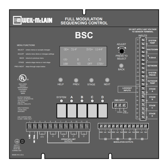
MENU FUNCTIONS
SELECT
enters menus or accepts changes
ADJUST
selects menu items or changes settings
BACK
returns to previous menu
STAGE
selects stage menus or next stage
PREV./NEXT
steps through output status
U L
C
US
R
ENCLOSED
ENERGY
MANAGEMENT
EQUIPMENT
LISTED
99RA
OUTPUT RATINGS:
120VAC, 6A RESISTIVE
1A PILOT DUTY
15A TOTAL
FOR ALL CIRCUITS
INPUT RATINGS:
115VAC 60Hz
30VA MAX
USE COPPER WIRE,
CLASS 1 WIRE ONLY
1
SAFETY
GROUND
MUST BE
CONNECTED
MADE IN U.S.A.
This Weil McLain control is strictly an operating control; it should never be used as a
WARNING
primary limit or safety control. All equipment must have its own certified limit and safety
controls required by local codes. The installer must verify proper operation and correct any
safety problems prior to the installation of this Weil McLain control.
BSC Installation and Operation Manual
BSC
BSC-BAC
BSC-8X
FULL MODULATION
SEQUENCING CONTROL
BSC
OD= 31
o
F
<A>
100
HELP
PREV.
A
SYSTEM
2
3
4
5
6
7
8
9
10
A
B
C
SYS
OPERATING LIMIT
OUTPUTS
ADJUST
SYS= 114
o
F
PRESS TO
SELECT
B
C
D
53
OFF
STBY
BACK
NEXT
STAGE
B
C
D
EMS INPUT
+
SIGNAL SHIELD
11
12
-
+
+
-
+
GND mA
Volt
GND mA
D
B
A
MODULATION OUTPUTS
Modulating Control
Modulating BACnet Control
Modulating Extension
DO NOT APPLY ANY VOLTAGE
TO SENSOR TERMINAL
INPUTS
T
A1
SYSTEM
TEMP
A2
A3
SHUTDOWN
A4
S
A5
4-20mA
A6
+
A7
NETWORK
A8
A9
SYSTEM
PROVE
A10
T
A11
OUTDOOR
TEMP
A12
LOCKOUT
B1
STAGE
INPUTS
A
B2
B3
STAGE
B
B4
B5
STAGE
C
B6
B7
STAGE
D
B8
+
-
+
+
-
+
+
Volt
GND mA
Volt
GND mA
Volt
D
C
550-100-074/0408
Advertisement
Table of Contents

Related Manuals for Weil-McLain BSC


Summary of Contents for Weil-McLain BSC
- Page 1 BSC Installation and Operation Manual Modulating Control BSC-BAC Modulating BACnet Control BSC-8X Modulating Extension MODULATING BOILER CONTROL WITH BACNET COMMUNICATION OPTION INSTALLATION AND OPERATION INSTRUCTIONS MANUAL FULL MODULATION SEQUENCING CONTROL DO NOT APPLY ANY VOLTAGE TO SENSOR TERMINAL INPUTS SYSTEM...
-
Page 2: Table Of Contents
Offset ..... 18 BSC OVERVIEW ....4 Minimum Water Temperature . -
Page 3: Bsc Function Chart
Green Ground 1-5V, 2-10V, 4-20mA, 0-135 Ohm. Different output pumps, valves or other screw must be boards mount on the back of the BSC to system components. connected to determine the type of output. Each N.O. output is wired in series Earth Ground with the each unit's limit circuit. -
Page 4: Bsc Overview
Controls 0-5V, 0-10V, 1-5V, 2-10V, 4-20 mA, or 0-135 modulating motors The BSC is designed to accurately control the output from 0 to 100% of modulation for each of these different types of motors. One BSC can even control two different types of motors. -
Page 5: Reset Ratio/Outdoor Reset
System Set Point based on outdoor temperature (Outdoor Reset) or it can modulate its stages 1:1.25 In Outdoor Reset, the BSC controls a hot water heating system to provide a building with comfortable and even heat levels. The BSC varies the temperature of the circulating heating 1.25:1... -
Page 6: Installation
Screw the cover to the base. snap-in location Mounting sensor and wall except from the bottom. screws location the control using the BSC Outdoor Sensor terminal marked with an “O” (A12). Shield not connected Outdoor Label ALERT on back of Sensor Outdoor... -
Page 7: Wiring The System Sensor
BSC Installation and Operation Manual WIRING THE SYSTEM SENSOR For proper operation, the BSC must be connected to a temperature or pressure sensor located in the common header. SYSTEM TEMPERATURE SYSTEM SYSTEM SENSOR TEMP SHIELD SHUTDOWN stages before any takeoffs. If the sensor cannot read the output of all the stages, it will not be able to control the system properly. -
Page 8: Wiring The System Prove
BSC activate and modulate the boilers as required to hold the set point. TEMP SYSTEM PROVE input is open on a call, the BSC will enable only the System Output. All Stage outputs will be off when the SYSTEM PROVE input is open. -
Page 9: Output Wiring
BSC Installation and Operation Manual OUTPUT WIRING SYSTEM WIRING THE SYSTEM OUTPUT System Output Operation in Set Point Mode SYSTEM PROVE input is shorted no Stages will be activated. If a Prove is not required, the factory- installed jumper should remain connected. -
Page 10: Modulating Output Card
Connect BACnet Ethernet Cat-5 cable to Communication RJ45 socket Board BACnet communication. Board Communication Board installed on the back of the BSC main board. BACnet RJ45 Communication socket on the BSC communication board. Motherboard BACnet HUB BACnet Network or Switch... -
Page 11: Wiring The Bsc To Extension Panels
BSC Installation and Operation Manual WIRING THE BSC TO EXTENSION PANELS Each extension has 8 stages with lockout inputs. The BSC can manage the Extension panels using an RS485 connection. necessary cables come with the extension panel. on the main BSC board to the enclosure. -
Page 12: Using The Menus
STAGE modulation status below. DISPLAY STAGE MODULATION STATUS DISPLAY MESSAGES The BSC normal display layout reserved the second line from the top for message indications. The following is a list of the most page 20. Lag Delay on page 20. -
Page 13: System Startup
External Set Point (4-20mA EMS Input) system parameters. See Wiring External Set Point on page 7. EMS terminals. If the BSC does not receive a signal between 2mA and 22mA, it will Shutdown by EMS... -
Page 14: Menu Settings
BSC Installation and Operation Manual MENU SETTINGS SET POINT & RESET ---- RESET RATIO ---- ------ SETTINGS ------ 1.00 OD=4.00 Sys Reset Set Point 140 F 1.00 OD=3.00 Sys Gain 1.00 OD=2.00 Sys ---- SET POINT ---- Lead Stage 1.00 OD=1.50 Sys 140 F <System Settings>... -
Page 15: Menu Settings Continued
BSC Installation and Operation Manual MENU SETTINGS CONTINUED LEAD AUTO ROTATE ------ SETTINGS ------ SYSTEM SETTINGS1 Manual Set Point 140 F Time Gain SYSTEM SETTINGS 1 Last On Lead Stage Auto Rotate Time <System Settings> Purge Delay 1.0min <System Startup>... -
Page 16: 20Ma Set Points
4-20MA, 0-5V, 0-10V, 1-5V, OR 2-10V OUTPUTS A & B. The BSC will then automatically bring up the screen for stages C & D. C & D can be selected to have a different Output Type from stages A & B. -
Page 17: Heat/Cool Mode
BSC Installation and Operation Manual HEAT/COOL MODE ---- HEAT/COOL ---- Heat, Cool Default: Heat Heat SELECT: MENU/<System Startup>/../Modulating Mode/Operating Mode/Heat-Cool Cool stages when the system is below the set point. In addition, the system relay will Outdoor Cutoff setting. -SENSOR FAULT MODE... -
Page 18: Reset Ratio
140 F SELECT: MENU/Set Point/Reset Ratio/Offset/Outdoor Cutoff/Min Wtr Temp (Available with Reset Modes Only) the Reset Ratio, and the Offset value. The BSC will control all boilers to hold either the Set Point temperature, or the Minimum Target, whichever is higher. -
Page 19: Gain/Throttle
NORMAL OPERATING MODE 1 ), the Gain adjusts the aggressiveness of the BSC PID logic to control how much modulation is changed when the system temperature/pressure is different from the Set Point. It is based on he rate of change. -
Page 20: Purge Delay
(Not Available in Process) line and can begin generating heat. to fully come on line and to begin producing output. Once the Purge Delay is over, the BSC can begin adjusting its modulation. MUST run through the entire Purge Delay period. -
Page 21: System Run-On
SELECT: MENU/System Settings/More Settings/Last-Stage-Hold (Not Available in Process) minimum output of one stage. When the BSC brings on the Lead Stage, the Set Point is quickly exceeded, and the Lead Stage is turned off. To prolong the run time during selected, before the Lead Stage is turned off. -
Page 22: Set Point And Default Table
AVOID CONFLICTING BOILER LIMITS WARNING The limits set on the boilers MUST be set considerably higher than the BSC's Set Point for the reasons detailed below: header will be lower than that registered by sensors in the boilers. Hold setting must be accounted for. The boiler limit must be set above the Set Point PLUS the Last-Stage-Hold PLUS the normal temperature drop experienced in the piping. -
Page 23: Security
BSC Installation and Operation Manual SECURITY PASSWORD ENABLED? ENABLE THE PASSWORD Yes, No Default: No SELECT: MENU/System Settings/More Settings/Password ------- LOGIN ------- ENTER PASSWORD M*** should change. CHANGE PASSWORD? DO NOT forget the Password. Write it down -- NEW PASSWORD -- the Password. -
Page 24: Stage Settings
BSC Installation and Operation Manual STAGE SETTINGS Press the STAGE button to --- STAGE A MODE--- go to the Stage Menu Auto Manual STAGE A SETTINGS Standby Mode Auto Ignition% Mod Start Copy Settings ------- STAGE A ------- Ignition Point... -
Page 25: Ignition
BSC Installation and Operation Manual MODE Auto - Auto can be Lead Stages. Standby - Standby Stages can only be activated when all Stages in Auto have been at 100% modulation for a selectable period of load conditions. A Standby Stage Cannot be a Lead Stage. -
Page 26: Copy Settings (Stage A Only)
BSC Installation and Operation Manual MODULATING MODE - NORMAL (SEE STARTUP MODULATING MODE ON PAGE 16) set point control. - Less than 50% - not recommended in the Normal Modulating Mode. - 50%-70% - These lower settings might be used in an application that has wide load swings such as an industrial plant or a hospital. -
Page 27: Maintenance
--- STAGE B TRIM --- +0.0 Stage A Trim clicking on the Stage button, BSC will scroll through the rest of the stages. range to make sure the results match your expectation. ALERT DO NOT use the Output Trim for a Stage unless it is absolutely necessary. Test burner operation and modulation output matching after adjusting the Output Trim. -
Page 28: Bacnet Communication
A BSC that is BACnet capable will display -- NETWORK PANEL -- on the 2nd row of the display when it is in screen saver mode. See page 12. BSC BACNET VARIABLE LIST The following is the BACnet variable list that can be used to communicate with the BSC. READ OBJ ID... - Page 29 BSC Installation and Operation Manual READ OBJ ID OBJECT NAME DESCRIPTION TYPE* RANGE / STATES ONLY 1=(inactive), LOCK00 through LOCK19 Lockout Input through919 2=Lockout,3=Comm Error Psi (56), °C(62), 1000 LSTHOLD Last-Stage-Hold 0 - 3.0psi, 0 - 30psi °C °F °F(64)
-
Page 30: Troubleshooting
5). If excessive heat occurs year round, reduce the Offset. - The BSC will only modulate boilers their mode is set to Auto or Standby. Check to if any boiler stage is set to Manual or On. See Mode on page 24. - Page 31 BSC Installation and Operation Manual Too Little Heat - If reduced heat occurs only in certain weather conditions, adjust the Reset Ratio and Offset (See 5). If reduced heat occurs year round, increase the Offset. reduce the Setback setting (See page 21) or change the hours the setback signal is activated.
-
Page 32: Bsc Specifications
BSC Installation and Operation Manual BSC SPECIFICATIONS Voltage Input: ...........
Need help?
Do you have a question about the BSC and is the answer not in the manual?
Questions and answers